Electric trolley for hanging empty rail
A tram and hoisting technology, which is applied to tracks, motor vehicles, elevated railway systems using suspended vehicles, etc., can solve the problems of difficulty in manufacturing, inconvenient maintenance, and high cost, and achieves simple construction, easy disassembly, and climbing ability. strong effect
- Summary
- Abstract
- Description
- Claims
- Application Information
AI Technical Summary
Problems solved by technology
Method used
Image
Examples
Embodiment 1
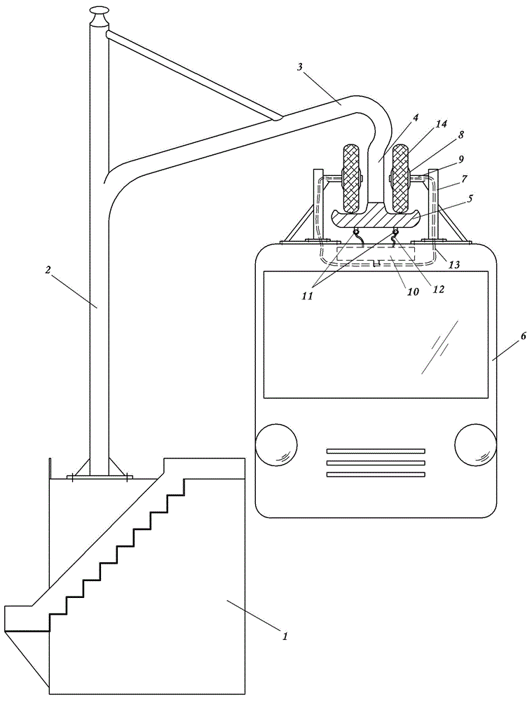
[0027] Embodiment 1: see figure 1 , a new empty rail suspension tram, the support rod 2 and the cantilever 3 form a bracket, the support rod 2 is evenly distributed and deeply buried and fixed on the ground (for example, in the lawn next to the road), and can be supported by steel frames or cement.
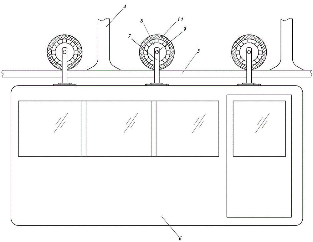
[0028] The cantilever 3 is generally horizontal or inclined upward, and is reinforced by a support rod or a tie rod. A vertical boom 4 is arranged at the end of the cantilever 3, and the lower end of the boom 4 is welded with a fixed track plate 5, which is bilaterally symmetrical, and the boom 4 and the track plate 5 form an inverted “T” or “mountain” structure.
[0029] The upper part of the tram car 6 is provided with a hanger 7, and the hanger 7 is horizontally fixed with symmetrical left and right motor shafts 8, and a motor 9 is respectively installed on each motor shaft 8, and the stator of the motor 9 is arranged on the motor shaft 8. The rotor of 9 is installed on the mo...
Embodiment 2
[0035] Example 2: see Figure 4 , the content is basically the same as that of Embodiment 1, and the similarities will not be repeated. The difference is that a damping mechanism is also arranged between the hanger and the tram car. The mode of damping mechanism is various, and the damping mechanism in the present embodiment is to be provided with horizontal positioning plate 21 at the bottom of hanger, and vertical guide hole is provided on positioning plate 21, and vertical guiding hole is fixed on the top of tram car. Column 22, the guide column 22 is matched with the guide hole, and the upper end of the guide column 22 protruding from the guide hole is provided with a blocking plate 23, and a spring 24 is installed between the blocking plate 23 and the positioning plate 21.
Embodiment 3
[0036] Embodiment 3: see Figure 5 , the content is basically the same as that of Embodiment 1, and the similarities will not be repeated. The difference is that an annular slot 15 is provided on the outer edge of the stator, and a matching rail 16 is provided on the upper side of the track plate, and the slot 15 and The clip rail 16 is fitted together.
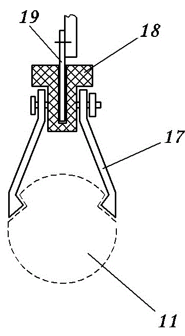
[0037] The power cord 11 is fixed on both sides of the track plate 5 in parallel. A sliding mechanism is provided between the power line 11 and the controller input line 12, and the sliding mechanism is a brush 20 capable of elastic contact with the power line, or a shrapnel capable of elastic contact with the power line.
PUM
 Abstract
Description
Claims
Application Information
 - R&D
- Intellectual Property
- Life Sciences
- Materials
- Tech Scout
- Unparalleled Data Quality
- Higher Quality Content
- 60% Fewer Hallucinations
Browse by: Latest US Patents, China's latest patents, Technical Efficacy Thesaurus, Application Domain, Technology Topic, Popular Technical Reports.
© 2025 PatSnap. All rights reserved.Legal|Privacy policy|Modern Slavery Act Transparency Statement|Sitemap|About US| Contact US: help@patsnap.com


