Vehicular braking energy recovery device
An energy recovery device and energy recovery technology, applied in the direction of machine/engine, mechanical equipment, engine, etc., to achieve the effect of simple structure, broad application prospect and small size
- Summary
- Abstract
- Description
- Claims
- Application Information
AI Technical Summary
Problems solved by technology
Method used
Image

Examples
Embodiment 1
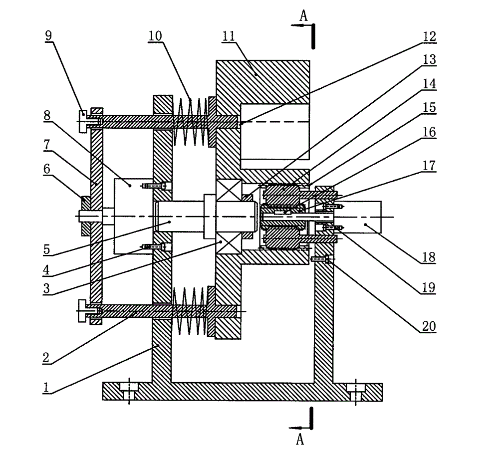
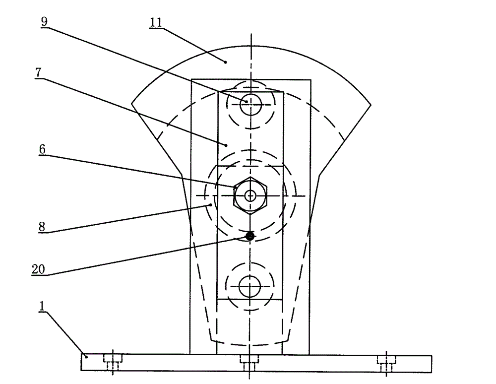
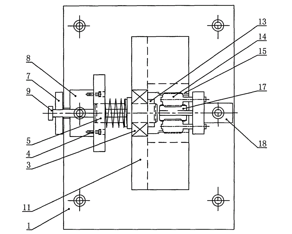
[0023] figure 1 In the shown embodiment, when there is no brake, there is no brake signal 25, the controller 26 has no control signal output, the solenoid valve 27 does not act, and the cylinder rod of the cylinder 8 is in a retracted state. Under the action of the compression spring 10, the positioning pin 2 is inserted into the positioning hole 12 on the energy recovery block 11, and the energy recovery block 11 is locked. The whole device is in a state of non-power generation. When braking, the controller 26 receives the braking signal 25, and outputs a control signal to the solenoid valve 27, and the cylinder 8 acts to drive the cylinder top plate 7 to lift the positioning pin 2 away from the energy recovery block 11. The mass eccentric energy recovery block 11 rotates around the fixed axis 5 under the action of inertia. The internal gear 15 on the energy recovery block 11 drives the central gear 17 to rotate at a high speed through the planetary gear 14, drives the gene...
Embodiment 2
[0025] Image 6 In the shown embodiment, when there is no brake, the electromagnet 21 is not energized, and the two positioning pins 2 are inserted into the positioning holes 12 on the side of the energy recovery block 11 under the action of the compression spring 10, and the energy recovery block 11 is locked in a vertical position. , the device is in a non-generating state. When braking, the controller 26 receives the braking signal 25 and outputs a control signal to the electromagnet 21 . The electromagnet 21 acts, and the electromagnet iron core 22 lifts the positioning pin 2 away from the energy recovery block 11 through the cylinder top plate 7 fixedly connected thereto. The energy recovery block 11 rotates around the fixed shaft 5 under inertia, and drives the generator 18 to generate electricity. When the vehicle brake pedal is released, no brake signal 25 is input to the controller 26, and the speed of the energy recovery block 11 decreases. When the output of the ...
Embodiment 3
[0027] Figure 7 In the shown embodiment, when there is no brake, there is no brake signal 25, the controller 26 has no control signal output, the solenoid valve 27 does not act, and the cylinder rod of the cylinder 8 is in a retracted state. Under the action of the compression spring 10 , the friction block 23 is inserted into the recess 24 on the energy recovery block 11 to lock the energy recovery block 11 . The device is in non-generating state. When braking, the controller 26 receives the braking signal 25 and outputs a control signal to the solenoid valve 27, and the cylinder 8 acts to drive the cylinder top plate 7 to lift the friction block 23 away from the energy recovery block 11. The energy recovery block 11 rotates around the fixed shaft 5 under inertia, and drives the generator 18 to generate electricity. When the vehicle brake pedal is released, no brake signal 25 is input to the controller 26, and the speed of the energy recovery block 11 decreases. When the ...
PUM
 Abstract
Description
Claims
Application Information
 - R&D Engineer
- R&D Manager
- IP Professional
- Industry Leading Data Capabilities
- Powerful AI technology
- Patent DNA Extraction
Browse by: Latest US Patents, China's latest patents, Technical Efficacy Thesaurus, Application Domain, Technology Topic.
© 2024 PatSnap. All rights reserved.Legal|Privacy policy|Modern Slavery Act Transparency Statement|Sitemap