Coil part and manufacturing method therefor

A technology of coil components and coils, which is applied in the manufacture of motor generators, electrical components, electric components, etc. It can solve the problems of affecting the fit of pin connectors, difficulty in taking out injection molded parts, and low operating efficiency, so as to achieve reliable insulation performance and high production efficiency. Efficiency improvement, easy loading and unloading effect

Active Publication Date: 2013-02-06
ZHEJIANG SANHUA INTELLIGENT CONTROLS CO LTD
View PDF5 Cites 10 Cited by
  • Summary
  • Abstract
  • Description
  • Claims
  • Application Information

AI Technical Summary

Problems solved by technology

[0003] In the prior art, the stator assembly of the coil component is placed in the injection mold for injection molding. Specifically, the pins are directly inserted into the injection mold for positioning, and then injection molding is performed. In this way, on the one hand, due to the large number of pins, It will take a long time to load and unload when matching with the mold; in addition, during the injection molding process, part of the injection material will flow out from around the pin, which will affect the cooperation between the pin and other connecting parts; and it will be relatively difficult to take out the injection molded part after injection molding Some
In addition, if the pins are divided into upper and lower rows, since the size of the pins is relatively small and the distance between adjacent pins is also small, the pins should be inserted into the corresponding pin holes when the stator assembly is loaded into the injection mold , the work efficiency is low; in particular, since the pin part needs to be welded with the cable, the plane part of the injection molded part exposed by the pin is not allowed to have injection molding burrs, which requires that the matching pin holes on the mold should not have chamfers. The above requirements Makes it less efficient for the pins to fit into the pin holes of the mold

Method used


Image

  • Coil part and manufacturing method therefor
  • Coil part and manufacturing method therefor
  • Coil part and manufacturing method therefor

Examples


Embodiment Construction

[0047] The core of the present invention is to make it more convenient to disassemble the stator assembly of the coil component during injection molding, and at the same time solve the problem of fixing the pins of the coil component during injection molding, thereby improving production efficiency. Hereinafter, in conjunction with the accompanying drawings of the specification, a coil component of an electronic expansion valve and a manufacturing method thereof will be used to specifically describe the embodiments of the present invention. In the following description, the structure of the coil component and the manufacturing method will be described together.

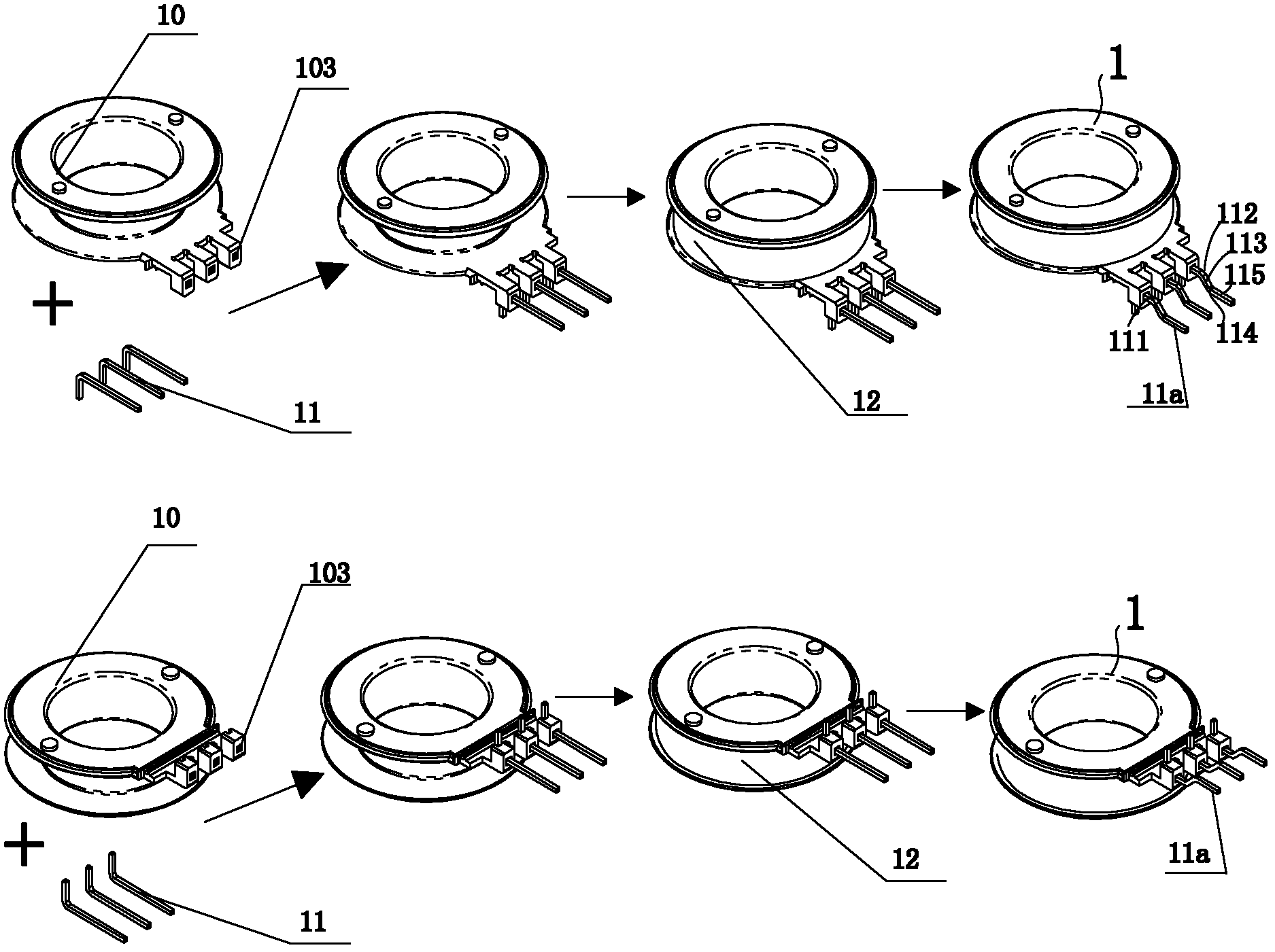
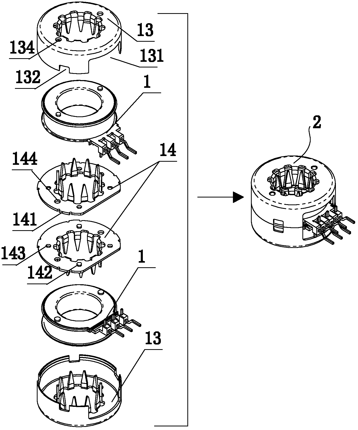
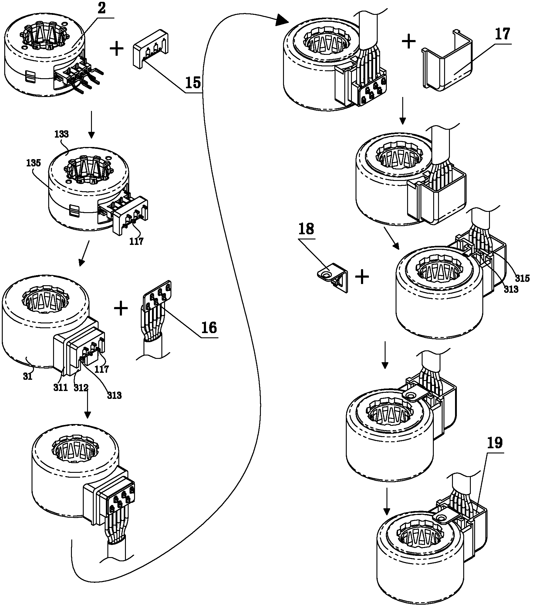
[0048] The manufacturing method of the electronic expansion valve coil component of the present invention includes the following steps completed in sequence:

[0049] 1. Processing of various parts: including frame 10 through injection molding, pin 11, stator shell 13, electromagnetic pole plate 14 stamping, and pin protect...


PUM


Abstract

The invention discloses a coil part, which comprises a stator component, wherein the stator component comprises stator shells, electromagnetic polar plates and stator windings, and each stator winding is provided with three contact pins. The coil part also comprises contact pin protection elements, wherein a contact pin holes correspondingly matched with the stator component are arranged on each contact pin protection element, the contact pin on the stator component is inserted into the contact pin hole of the contact pin protection element and exposed out of the outer surface of the contact pin protection element, the contact pin protection element and the stator component are assembled together and then are subjected to injection molding to form a coil injection molding piece, an injection molding layer of the coil injection molding piece is coated with an insulated separation bars of the contact pin protection elements and is not coated on the end part of the contact pin, which stretches out of the contact pin protection element or the outer surface of the contact pin protection element, which is back to the stator component. Based on the coil part, the invention also provides a manufacturing method for the coil part.

Description

Technical field [0001] The invention relates to the technical field of air conditioners, in particular to a coil component of a stepping motor, such as an electronic expansion valve coil component and a manufacturing method thereof. Background technique [0002] In the prior art, the electronic expansion valve outputs the power that changes according to the system parameters, and maintains the opening of the valve at a required position to maintain the liquid supply required by the evaporator. The coil cover of the traditional electronic expansion valve is installed on the outside of the valve body, and the coil and the rotor in the valve body constitute a motor; during operation, the rotor drives the inner valve stem of the valve body to adjust the opening degree. [0003] In the prior art, the stator assembly of the coil component is placed in an injection mold through injection molding. Specifically, the pins are directly inserted into the injection mold for positioning, and the...

Claims


Application Information

Patent Timeline
Patent Type & Authority Applications(China)
IPC IPC(8): H02K3/50H02K3/04H02K15/00
CPCY02B30/72Y02B30/70
Inventor 不公告发明人
Owner ZHEJIANG SANHUA INTELLIGENT CONTROLS CO LTD
Why Eureka
Try Eureka