
Motor vehicle collision device with differential-pressure stop valve

A technology of collision device and cut-off valve, which is applied in the direction of bumpers, etc., can solve the problems of poor anti-rear collision performance, anti-frontal collision performance, failure to reach the collision curve, and inability to absorb kinetic energy, etc.

Inactive Publication Date: 2013-02-13
凌建军
View PDF1 Cites 2 Cited by
  • Summary
  • Abstract
  • Description
  • Claims
  • Application Information

AI Technical Summary

Problems solved by technology

In addition, the anti-rear collision performance of existing motor vehicles is obviously worse than the anti-frontal collision performance, which is the main reason for the relatively high death rate in rear-end collision accidents.
[0004] The patent 201010549637.8 submitted by the applicant discloses a motor vehicle collision device with a switch-controlled energy consumer. This patent can well solve the complete frontal collision of the car and can completely absorb all the energy of the motor vehicle. In addition, this patent still exists The following problems: ① Cannot solve the problem of absorbing energy in the process of offset collision
If the offset collision (40% offset) occurs on the left side of the motor vehicle, only the left piston push rod pushes back with the piston, and only the left switch-controlled energy consumer consumes energy. The switch-controlled energy consumer on the left side of the effective stroke cannot absorb the kinetic energy of the entire motor vehicle; ② when processing the pressure relief holes (1615, 1629) and the high-pressure communication holes (1613, 1627), the process holes must be drilled, and then the process holes must be drilled. Plugging with screws or welding; ③When the drill hole reaches the bottom of the upper valve cylinder (1607, 1621), the drill bit is easily damaged due to asymmetry; ④In the later stage of the collision, because the switch valve stem assembly will gradually close, A larger proportion of antifreeze enters the annular space between the piston cylinder and the piston top rod, and the pressure in the annular space between the piston cylinder and the piston top rod will increase rapidly from negative pressure to high pressure, and the pressure relief valve with holes ( 1616, 1630) will close the pressure relief hole (patent 201010549637.8 Figure 13 ), once the pressure in the annular space is greater than a certain value, the switch valve stem assembly will be forcibly pulled up, the effective injection hole area will suddenly increase, and the pressure in the pressure guide tube will drop rapidly, resulting in a decrease in the acceleration of the B-pillar in the later stage of the collision. Cannot reach the ideal collision curve

Method used


Image

  • Motor vehicle collision device with differential-pressure stop valve
  • Motor vehicle collision device with differential-pressure stop valve
  • Motor vehicle collision device with differential-pressure stop valve

Examples


no. 1 approach

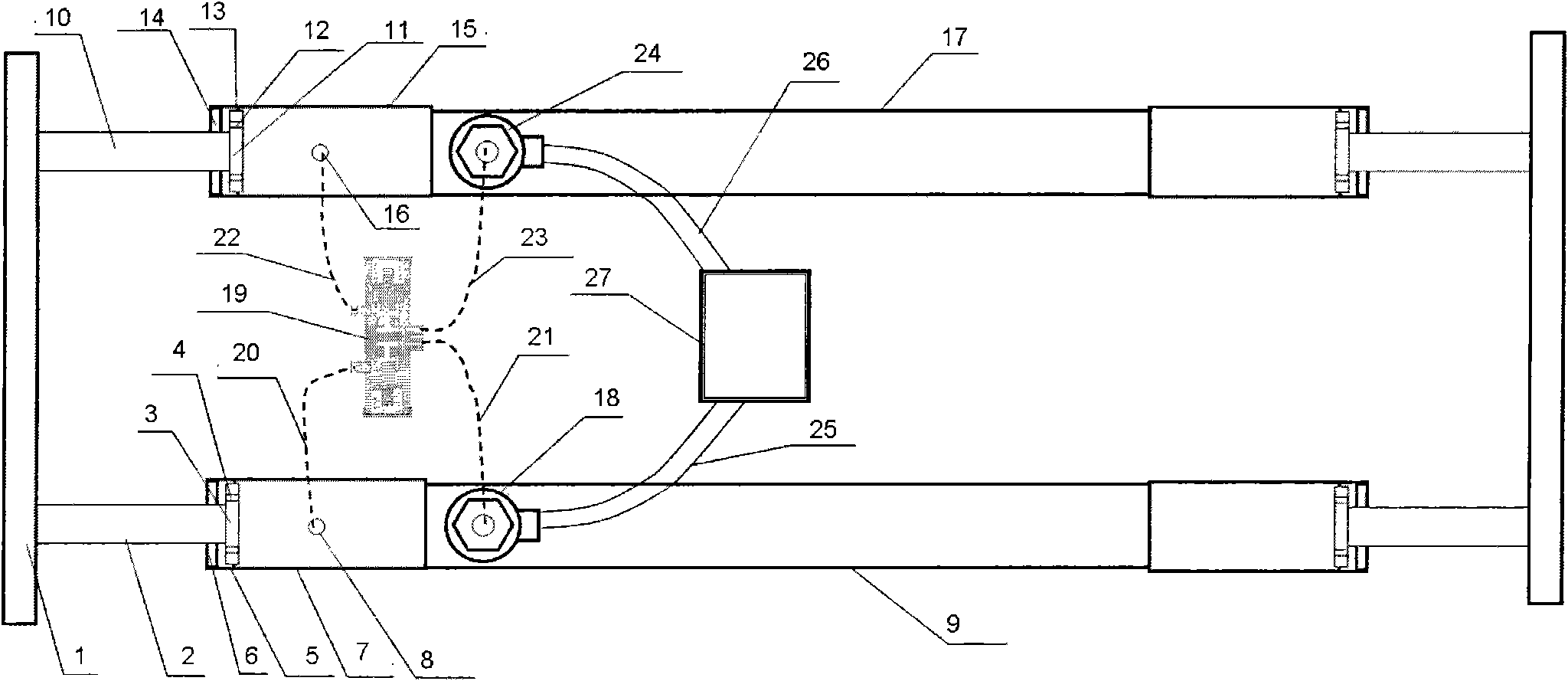
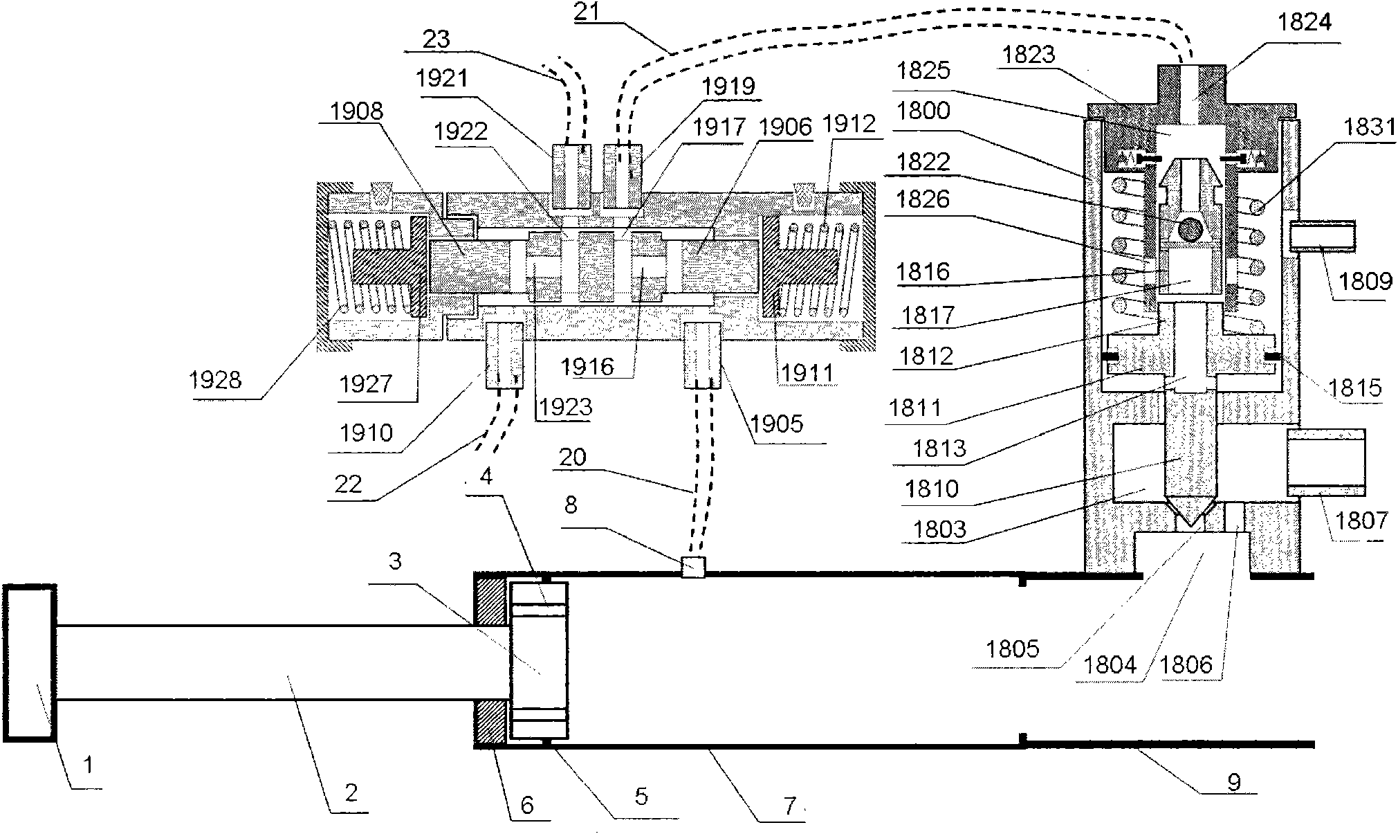
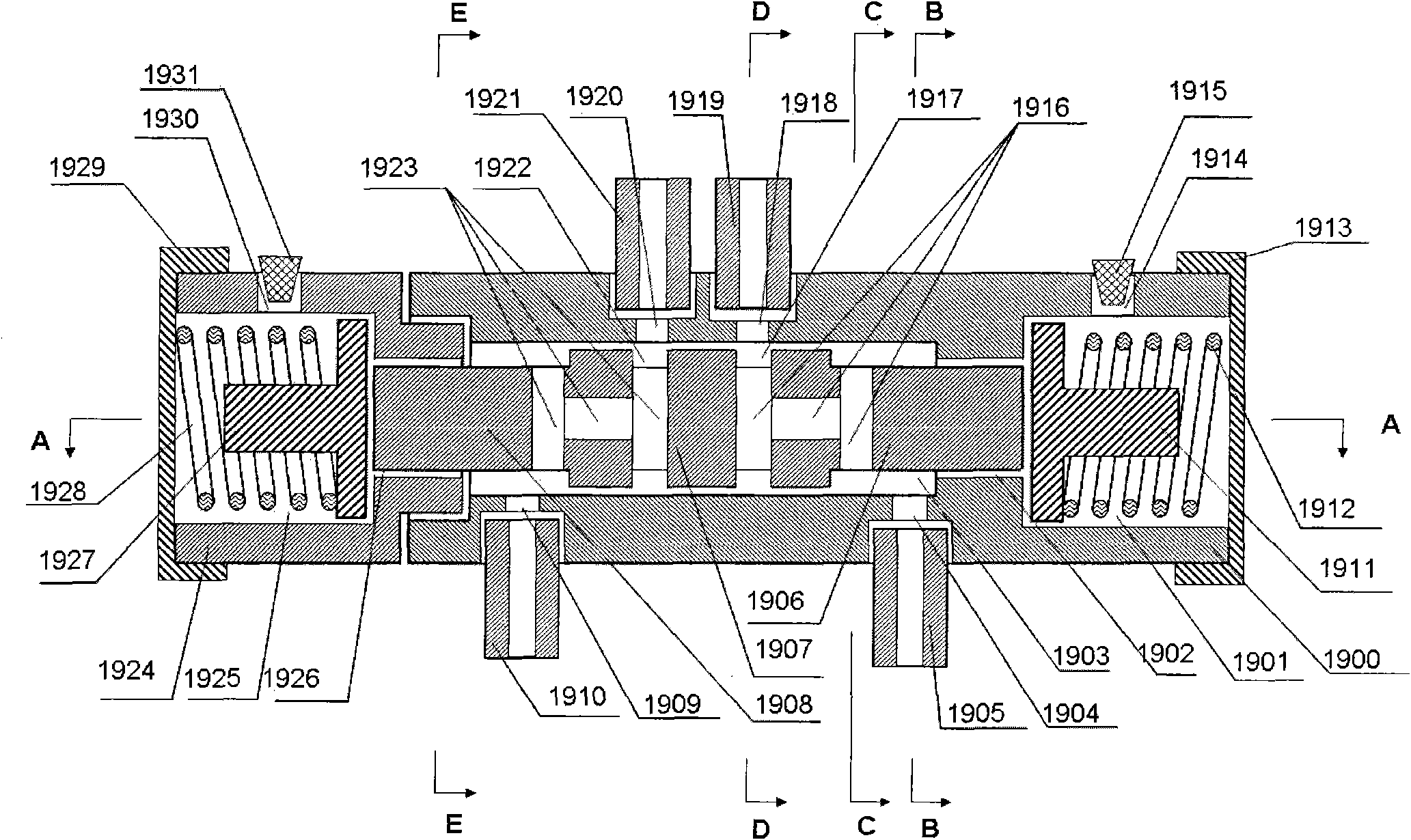
[0048] figure 1 It is a top view schematic diagram of a motor vehicle collision device with a differential pressure shut-off valve of the present invention; figure 2 It is a partial cross-sectional schematic diagram of a motor vehicle collision device with a differential pressure shut-off valve of the present invention; image 3 is a schematic cross-sectional view of a differential pressure stop valve; Figure 4 It is a schematic cross-sectional view of the A-A plane of the differential pressure stop valve; Figure 5 It is a schematic cross-sectional view of the B-B plane of the differential pressure stop valve; Figure 6 It is a schematic cross-sectional view of the C-C plane of the differential pressure stop valve; Figure 7 It is a schematic cross-sectional diagram of the D-D plane of the differential pressure stop valve; Figure 8 It is a schematic cross-sectional view of the E-E plane of the differential pressure stop valve; Figure 9 is a cutaway view of the switc...

no. 2 approach

[0063] Figure 17 It is a schematic cross-sectional view of the second embodiment of the differential pressure stop valve; the principle of the second embodiment is basically the same as that of the first embodiment, the only difference is that an opening sealing nipple 1934 is added; the sealing nipple with holes is added 1934 is between the first shut-off valve seat 1900 and the second shut-off valve seat 1924 .

no. 3 approach

[0065] Figure 18 It is a schematic cross-sectional view of the third embodiment of the differential pressure cut-off valve; the principle of the third embodiment is basically the same as that of the first embodiment, the only difference is that there is a first cut-off valve stem seal on the right section of the cut-off valve stem 1906 Ring groove 1935; there is a second cut-off valve stem seal ring groove 1937 in the left cut-off valve stem 1908; the first cut-off valve stem seal ring groove 1935 and the second stop valve stem seal ring groove 1937 Installed with sealing rings (1936, 1938).


PUM


Abstract

A motor vehicle collision device with a differential-pressure stop valve comprises at least two piston cylinders, at least two pistons, at least two piston cylinder screw hole connectors, at least four high-pressure connection pipes, at least two switch control energy dampers and a differential-pressure stop valve; the differential-pressure stop valve comprises a stop valve substrate assembly, a stop valve rod assembly, a first T-shaped top plate, a second T-shaped top plate, a first top-plate spring, a second top-plate spring, a first end cover and a second end cover; and when the difference of the hydraulic force applied on an annular area of the first stop valve rod and the second stop valve rod is greater than the advance-applied force of the top plate springs, the pressure connection between the first high-pressure connection pipe and a second high-pressure connection pipe as well as between the third high-pressure connection pipe and the fourth high-pressure connection pipe is disconnected by the stop valve rod assembly, so that a switch valve rod assembly at the early state of the offset collision can be prevented from being forcedly opened in advance, and the offset collision capacity of a motor vehicle can be greatly improved.

Description

technical field [0001] The invention relates to a motor vehicle collision device, in particular to a motor vehicle collision device with a differential pressure stop valve. Background technique [0002] Since the advent of motor vehicles in 1886, while bringing convenience to human life and work, road traffic accidents have also caused a large number of casualties and property losses. So far, more than 34 million people have died in car accidents worldwide, while hundreds of millions of people have been injured or disabled. According to the "Global Status of Road Safety" report published by the World Health Organization (WHO) on June 15, 2009, the number of deaths involving road traffic accidents in 2008 was as high as 1.2 million, and 20 to 30 million were injured or disabled. The annual economic loss caused by traffic accidents exceeds 700 billion US dollars. [0003] The body of the existing motor vehicle is in a compressed state during the impact process. On the one ha...

Claims


Application Information

Patent Timeline
IPC IPC(8): B60R19/20
Inventor 凌建军黄鹂杨铸李越
Owner 凌建军
Learn More