Concentric sliding block simultaneous casing drilling tool, center drilling bit and centralizer

A guider and drill bit technology, which is applied in the direction of drill bits, drilling equipment, earthwork drilling, etc., can solve the problems of easy drilling, high pipe resistance, and out-of-round drilling, so as to reduce pipe pulling force and slag discharge speed The effect of fast and less slag falling back

Active Publication Date: 2013-02-13
广汉珂普瑞科技有限公司
View PDF5 Cites 29 Cited by
  • Summary
  • Abstract
  • Description
  • Claims
  • Application Information

AI Technical Summary

Problems solved by technology

[0002] At present, most of the down-the-hole follow-up drilling tools sold in the market are eccentric follow-up drills. According to years of practice, the existing eccentric Tube drilling tools or other concentric drilling tools have obvious defects, such as large torque force, out-of-round drilling, easy drill sticking, high pipe resistance, large eccentric swing, uneven force on the drilling tool during use, Poor strength, must be reversed when pulling back, and prone to technical defects such as broken drill pipes and casings

Method used


Image

  • Concentric sliding block simultaneous casing drilling tool, center drilling bit and centralizer
  • Concentric sliding block simultaneous casing drilling tool, center drilling bit and centralizer
  • Concentric sliding block simultaneous casing drilling tool, center drilling bit and centralizer

Examples


Embodiment 1

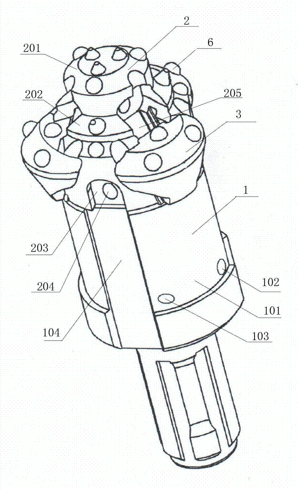
[0043] The central drill bit of the present invention includes a drill bit body 201 and a reaming drill piece 3. The drill bit body 201 has a front part, a middle part and a tail part along its central axis, and the front part, the middle part and the tail part are integrally structured. The front part of the drill bit body 201 is The middle part of the drill body 201 has an arrow-shaped structure. The diameter of the middle part of the drill body 201 is larger than that of the front part. At least two inclined grooves 208 are provided on the outer peripheral surface of the drill bit body 201 from the front part to the middle part. Groove, make chute 208 be the guide groove of T-shaped structure, this chute 208 can be 2, 3, 4, 5 or more, present embodiment preferably uses 2 chute 208, and 2 chute The grooves 208 are evenly distributed on the outer peripheral surface of the drill body 201 at intervals of 180° relative to the central axis, and any inclined groove 208 is matched w...

Embodiment 2

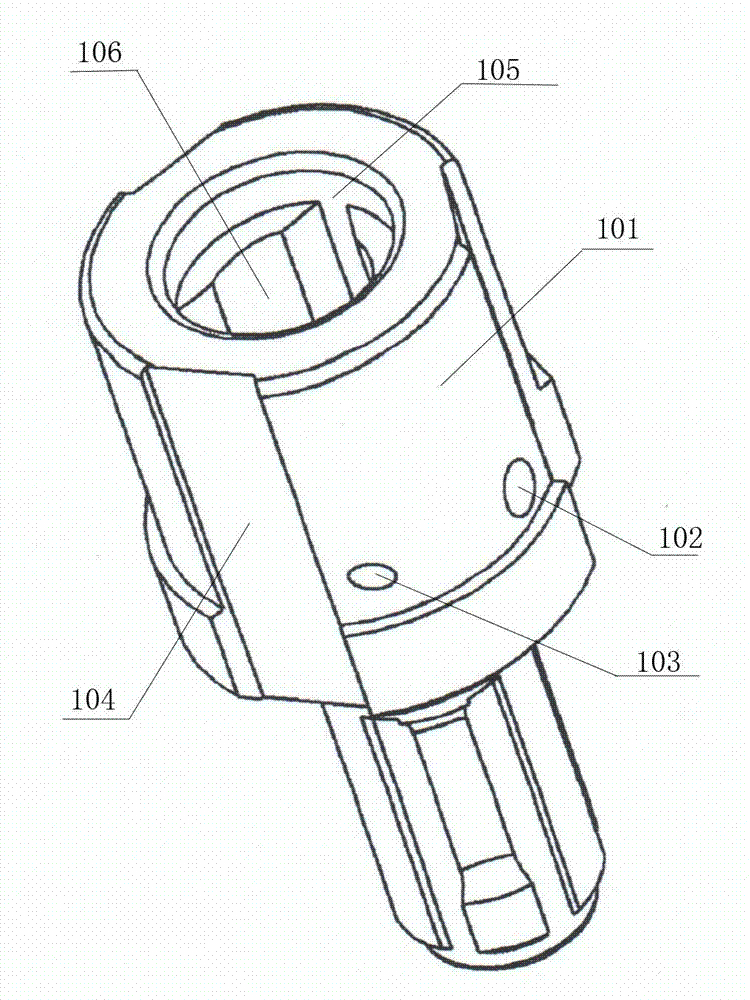
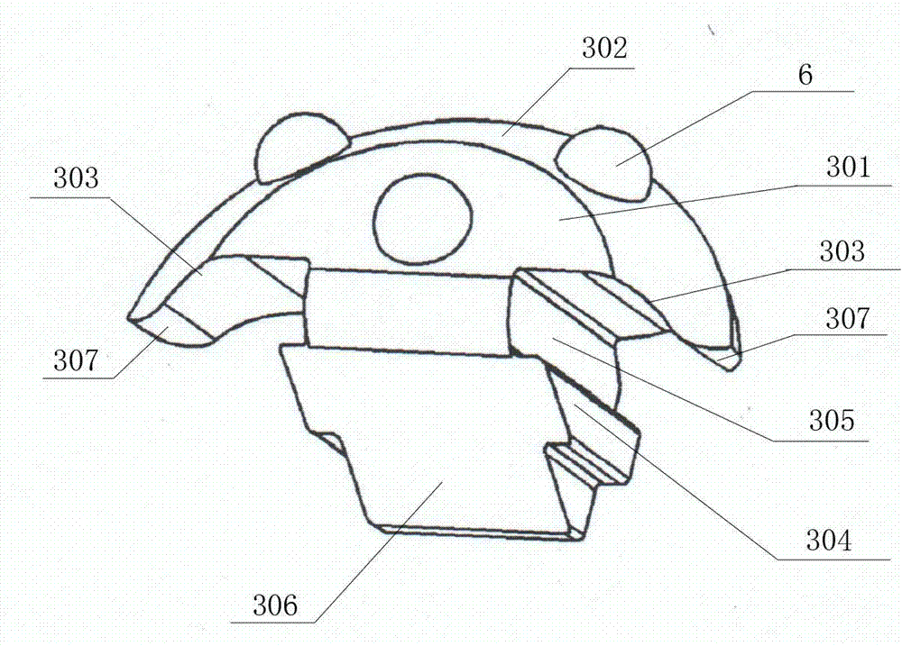
[0048] Embodiment 2 On the basis of Embodiment 1, the front part of the drill body 201 has a conical structure; the front part and the middle part of the drill body 201 have a truncated cone-shaped slope transition, and the number of the inclined grooves 208 is four, and the four inclined The grooves 208 are evenly distributed on the outer peripheral surface of the drill body 201 at intervals of 90° relative to the central axis, any chute 208 is matched with a reaming drill piece 3, and rectangular grooves and trapezoidal grooves are arranged on the two side walls of the chute 208 Or any one among the dovetail grooves, make the chute 208 a guide groove of T-shaped structure, the present embodiment selects the dovetail groove, and the bump body 304 cooperates with the guide groove, especially cooperates with the dovetail groove, so as to facilitate expansion Hole drill piece 3 slides in guide groove, and the afterbody of described drill bit body 201 is hexagonal cylinder, and th...

Embodiment 3

[0050] Such as image 3 and Figure 4 As shown, Embodiment 3 is based on Embodiment 1. In the center drill bit of the present invention, the front part of the drill body 201 is a circular boss structure, so that the front part of the drill body 201 presents a stepped multi-stage boss. In this example A three-stage boss structure is adopted, that is, a three-stage stepped structure. Of course, a two-stage boss structure, a four-stage boss structure, a five-stage boss structure, or more boss structures can be used according to actual needs. The diameter of the bevel taper is transitional, so that the diameter of the drill body 201 is the smallest from the front end, and then gradually increases, and the transition is made through the bevel taper. In this embodiment, there are three chute grooves 208, and the three chute grooves 208 are relatively The central axis is evenly distributed on the outer peripheral surface of the drill body 201 at intervals of 120°, any chute 208 is m...


PUM


Abstract

The invention discloses a concentric sliding block simultaneous casing drilling tool, a center drilling bit and centralizer. The concentric sliding block simultaneous casing drilling tool is formed by the centralizer, a ladder-shaped tapping center drilling bit and semicircle-shaped expanding drilling pieces, wherein the ladder-shaped tapping center drilling bit is connected and matched with a hole to which the centralizer is aligned for torque transmission, the ladder-shaped tapping center drilling bit is connected and located through a locating groove, a locating hole, a solid cylindrical pin and a hollow expansion pin, three semicircle-shaped expanding drilling pieces are in torque transmission through a T-shaped oblique groove and an R arc-shaped oblique groove, mutual included angles of the T-shaped oblique groove and the R arc-shaped oblique groove are 120 degrees by using an axis of the ladder-shaped tapping center drilling bit as the center, the semicircle-shaped expanding drilling pieces slide backwards to the end surface of the centralizer along the T-shaped oblique groove and the R arc-shaped oblique groove when being subjected to rock resistance and can be located, an expanding simultaneous casing can be formed, and the semicircle-shaped expanding drilling pieces slide downwards, can be narrowed and withdrawn due to the resistance of a pipe boot during upward drawing. According to the concentric sliding block simultaneous casing drilling tool disclosed by the invention, the front area of the tapping drilling bit is small, the force is concentrated, and the tapping drilling bit can crush harder or large rocks firstly at stages at crushing speed.

Description

technical field [0001] The invention relates to the construction of deep and shallow hole broken sections of related projects such as mine blasting, hydropower infrastructure construction, road slope foundation reinforcement, railway survey, and geological disaster prevention; Core, deep foundation pit support, high slope anchorage, tunnel collapse pipe shed support, pebble layer high-pressure rotary spraying, etc., involving a concentric follower and pipe concentric slider follower pipe drilling tool for a down-the-hole hammer . Background technique [0002] Most of the down-the-hole drilling tools currently on the market are eccentric drilling tools. According to years of practice, the existing eccentric drilling tools or other concentric drilling tools have obvious defects, such as In the process of use, the torque force is large, the drilling is not round, the drill is easy to stick, the pipe resistance is large, the eccentric swing is large, the force of the drilling t...

Claims


Application Information

Patent Timeline
Patent Type & Authority Applications(China)
IPC IPC(8): E21B10/32E21B10/40E21B10/00E21B4/06
Inventor 马勇曾德明
Owner 广汉珂普瑞科技有限公司
Why Eureka
Try Eureka