Test method for hydraulics size of shear flow polymer and test device thereof

A shear flow and testing device technology, applied to measuring devices, instruments, etc., can solve problems such as flow field interference, large test errors, and difficulty in controlling the flow state, and achieve reduced test errors, simple operation, stability and accuracy sex high effect

Inactive Publication Date: 2013-02-13
SOUTHWEST PETROLEUM UNIV
View PDF5 Cites 11 Cited by
  • Summary
  • Abstract
  • Description
  • Claims
  • Application Information

AI Technical Summary

Problems solved by technology

However, this method has the following disadvantages: ① When the polymer solution passes through the micropores of the single-layer filter membrane, there is a cross flow, which causes the flow field between adjacent micropores to interfere with each other. It is difficult to control the flow state through the micropores during the test, and the test is stable. ② Since the filtration rate is controlled by constant pressure during filtration, the flow rate and shear rate of the polymer solution will change with the change of the filter membrane pore size, and the hydraulic size of the polymer will change when the shear yield flow However, this method cannot test the hydraulic size of the polymer at a certain shear flow rate. Therefore, the size of the polymer oil displacement agent tested by this method is different from the real flow form of the oil displacement agent in the reservoir medium. The compatibility research based on this is also inconsistent with the real situation; ③The mass concentration change of the polymer solution is directly used to reflect the interception and passage of the polymer on the filter membrane, because the concentration of the polymer solution used in the test is low , the test error is large

Method used


Image

  • Test method for hydraulics size of shear flow polymer and test device thereof
  • Test method for hydraulics size of shear flow polymer and test device thereof
  • Test method for hydraulics size of shear flow polymer and test device thereof

Examples


Embodiment 1

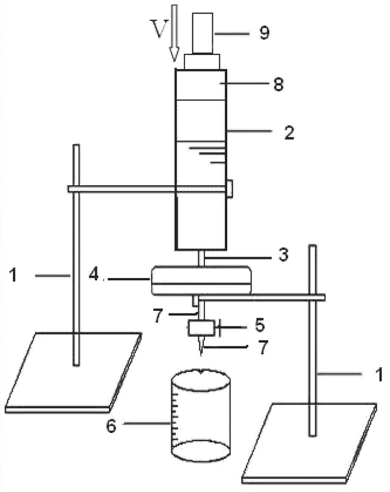
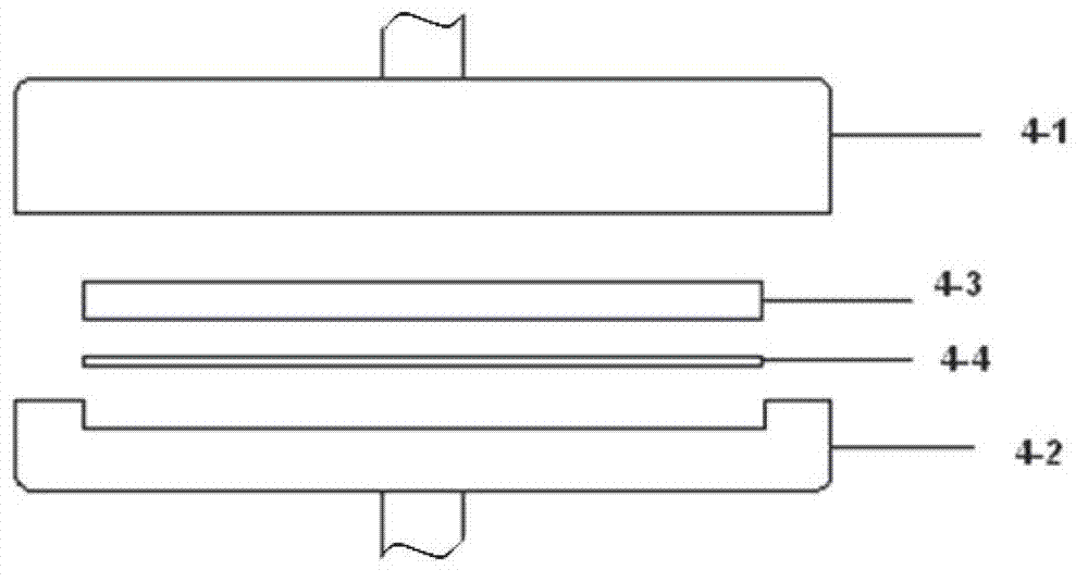
[0031] In this embodiment, the structure of the testing device for polymer hydraulic dimensions under shear flow is as follows: figure 1 As shown, the test device includes a liquid storage cylinder 2, a shear flow generator 4, a filtrate collection container 6 and a bracket 1 for supporting the liquid storage cylinder and the shear flow generator. The liquid storage cylinder 2 is equipped with a Matching piston 8, the lower end of the liquid storage cylinder communicates with the shear flow generator through the pipe fitting 3, and the structure of the shear flow generator is as follows figure 2 As shown, it consists of an upper chuck 4-1, a lower chuck 4-2, an upper filter membrane 4-3 and a lower filter membrane 4-4, and the upper filter membrane 4-3 and the lower filter membrane are placed in the lower chuck 4-2 On the top, it is fixed by the upper clamp 4-1, and the lower part of the lower clamp 4-2 is provided with a liquid outlet pipe 7, and a control valve 5 is install...

Embodiment 2

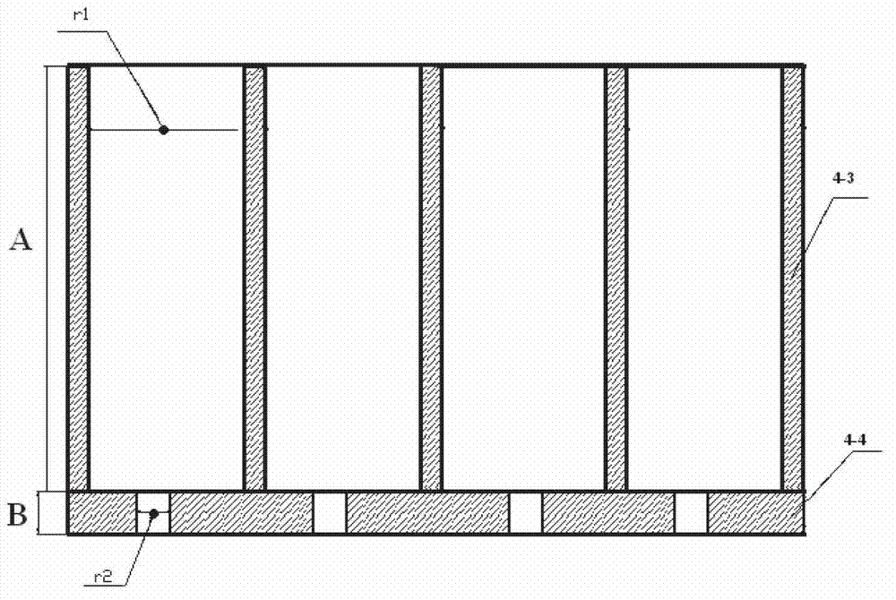
[0034] In this embodiment, the testing device described in Example 1 is used to test the hydraulic size of polyacrylamide, wherein the thickness A of the upper filter membrane=the aperture r of the upper filter membrane 1 (μm), the thickness of the lower filter membrane B = the lower filter membrane pore size r 2 (μm), the material universal testing machine (accuracy is 0.001mm / min, model MT6104, manufactured by Meister Industrial Systems Co., Ltd.) is used as the speed control device to control the movement speed of the piston, and the shear rate adopts the simple shear rate formula γ=( 16.67*v) / r 2 Calculation, where, γ is the shear rate (s -1 ), v is the piston movement rate (mm / min), r 2 is the pore size of the lower filter membrane (μm).

[0035] The operation steps of this embodiment are as follows:

[0036] ① Add polyacrylamide with a degree of hydrolysis of 9.78% to an aqueous solution of sodium chloride with a salinity of 5727mg / L to prepare a polyacrylamide solut...

Embodiment 3

[0051] In this example, the preparation method of the polyacrylamide solution is as follows: polyacrylamide with a degree of hydrolysis of 9.78% is added to a sodium chloride solution with a salinity of 5727 mg / L to prepare a polyacrylamide solution with a concentration of 800 ppm.

[0052] In the present embodiment, other experimental conditions are identical with embodiment 2, and test method is identical with embodiment 2, and testing shear rate is 28.8s respectively -1 、43.2s -1 、57.6s -1 、72s -1 , 86.4s -1 、100.8s -1 When the average hydraulic radius of polyacrylamide, the relationship curve between the viscosity retention rate and the corresponding lower filter membrane pore size is as follows Figure 5 As shown, the average hydraulic size of polyacrylamide at each shear rate is shown in Table 4.

[0053] Table 4 Average hydraulic dimensions of 800ppm polyacrylamide

[0054] (mineralization degree 5727mg / L)

[0055] Shear rate (s -1 ) 28.8 43.2 57.6 ...


PUM


Abstract

Provided are a test device and a test method for the hydraulics size of shear flow polymer. The device comprises a liquid barrel, a shear flow generator, a filter liquid collection container and a support for supporting the liquid barrel and the shear flow generator, wherein the liquid barrel is provided with a piston matched with the inner diameter of the liquid barrel, the lower end of the liquid barrel is communicated with the shear flow generator, the shear flow generator is composed of an upper chuck, a lower chuck, an upper layer filter membrane and a lower layer filter membrane, the upper layer filter membrane and the lower layer filter membrane are arranged on the lower chuck, a liquid outlet pipe is positioned at the lower portion of the lower chuck, a control valve is positioned on the liquid outlet pipe, and the filter liquid collection container is positioned under the liquid outlet pipe. The method using the test device comprises the steps of preparing polymer solution, filtering and drawing relation curve between viscosity retention rate and corresponding hole diameter of the lower layer filter membrane. When the viscosity retention is 70%, the hole radius of the corresponding lower layer filter membrane is the average hydraulics radius of the shearing rate.

Description

technical field [0001] The invention belongs to the field of polymer size testing, and in particular relates to a method for testing polymer hydraulic dimensions under shear flow and a testing device thereof. Background technique [0002] When the hydration molecules of the polymer oil displacement agent flow through the porous medium, the hydration molecules of the oil displacement agent are naturally selected by the size of the pore throat of the reservoir. The phenomenon that the agent blocks the formation, which leads to an increase in the injection pressure. Therefore, when designing a polymer flooding scheme, the polymer flooding agent must be compatible with the pore throat size of the reservoir medium, and the accurate measurement of the hydraulic size of the polymer flooding agent in different environments is the key to the study of polymer flooding. It is the key and prerequisite for the compatibility of pore throat size between the agent and the reservoir medium....

Claims


Application Information

Patent Timeline
Patent Type & Authority Applications(China)
IPC IPC(8): G01B21/10
Inventor 何显儒王煦张睿杨成玉肖长发余慧容耀强蔡术威侯海龙
Owner SOUTHWEST PETROLEUM UNIV
Why Eureka
Try Eureka