
Hydraulic adjusting loading device for self-weight type slide slope physical model experiment

A landslide physical model and loading device technology, applied in soil material testing, material inspection products, etc., can solve the problem of difficult to meet the fast, stable and continuous thrust loading requirements of the trailing edge of the landslide, difficult to accurately control the magnitude and direction of the landslide thrust, and the boundary of the landslide. Inconsistent conditions, etc., to achieve the effect of easy movement and transportation, easy repair or replacement, and easy operation

Inactive Publication Date: 2013-02-13
CHINA UNIV OF GEOSCIENCES (WUHAN)
View PDF7 Cites 15 Cited by
  • Summary
  • Abstract
  • Description
  • Claims
  • Application Information

AI Technical Summary

Problems solved by technology

[0005] (1) The thrust loading and control system of the trailing edge of the existing landslide physical model is often complex in structure and cumbersome in operation, and it is difficult to meet the requirements of fast, stable and continuous thrust loading on the trailing edge of the landslide;
[0006] (2) Although the existing artificial stacking method can apply a stable force on the trailing edge of the landslide, it is difficult to accurately control the magnitude and direction of the landslide thrust, and the boundary conditions of the applied external force do not match the actual situation

Method used


Image

  • Hydraulic adjusting loading device for self-weight type slide slope physical model experiment
  • Hydraulic adjusting loading device for self-weight type slide slope physical model experiment
  • Hydraulic adjusting loading device for self-weight type slide slope physical model experiment

Examples


Embodiment Construction

[0036] Specific embodiments of the present invention will be described in further detail below in conjunction with the accompanying drawings.

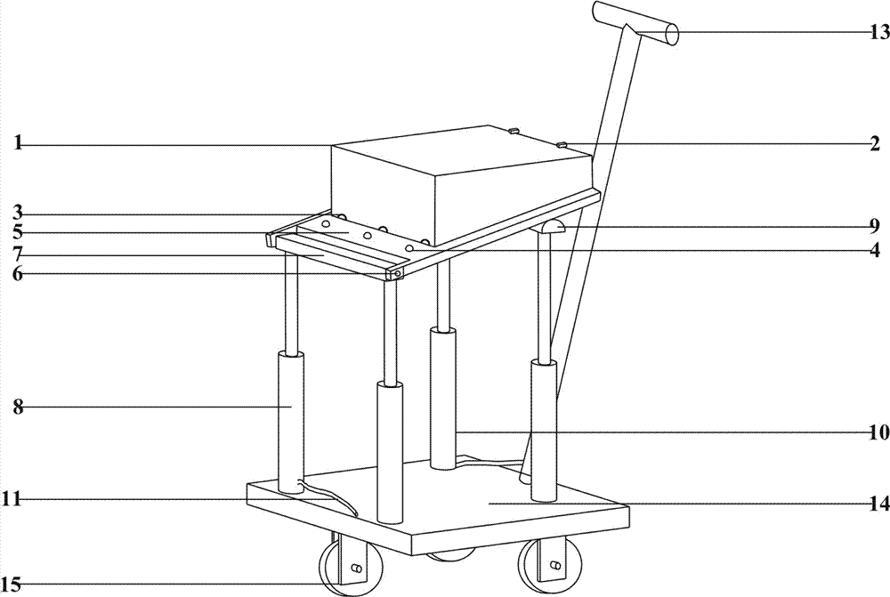
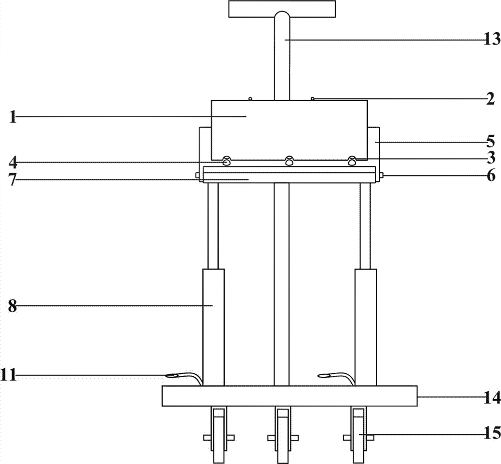
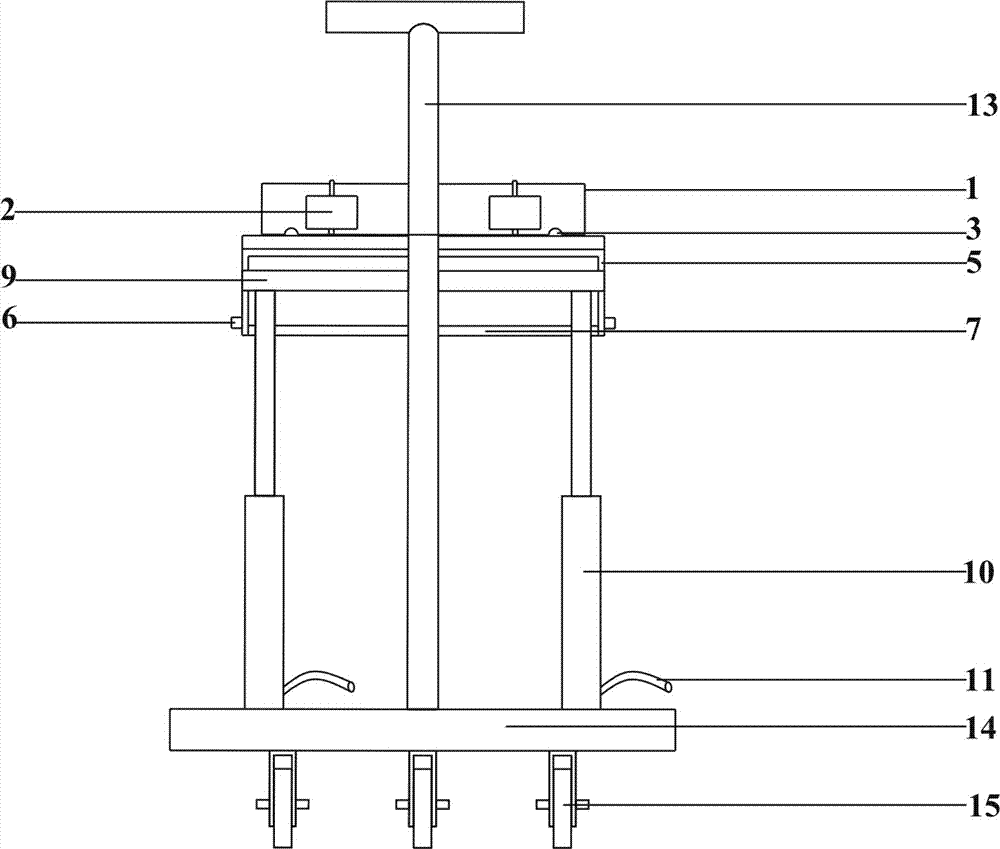
[0037] Such as Figure 1 to Figure 5 As shown, a self-weight landslide physical model test hydraulic adjustment loading device of the present invention includes a base 14, a sliding surface adjustment mechanism and a thrust loading mechanism, specifically as follows.

[0038] The base 14 below is provided with some walking wheels 15, so that the movement of the whole device, and the base is also provided with a handle 13, which is convenient for personnel to promote the device.

[0039] The sliding surface adjustment mechanism is located on the base 14. The sliding surface adjustment mechanism of the present embodiment includes a sliding panel 5, a front support plate 7, a pair of front hydraulic telescopic rods, a rear support plate 9 and a pair of rear hydraulic telescopic rods. The front hydraulic telescopic rod and the rear hydrau...


PUM


Abstract

The invention provides a hydraulic adjusting loading device for a self-weight type slide slope physical model experiment. The hydraulic adjusting loading device comprises a base, a sliding surface adjusting mechanism and a thrust force loading mechanism; the sliding surface adjusting mechanism is arranged on the base, the sliding surface adjusting mechanism comprises a sliding panel, a front support plate, at least one pair of front hydraulic telescopic links, a back support plate and at least one of back hydraulic telescopic links, the front hydraulic telescopic links are supported at the front of the base, the top ends of the front hydraulic telescopic links are connected with the front support plate, the back hydraulic telescopic links are supported at the back of the base, the top ends of the back hydraulic telescopic links are connected with the back support plate, the front end of the sliding panel is hinged with the front support plate, and the back end of the sliding panel is supported on the back support plate; and the thrust force loading mechanism comprises a loading platform for bearing heavy substances, and the bottom surface of the loading platform is in sliding fit with the top surface of the sliding panel, and can slide along the sliding panel front and back. According to the hydraulic adjusting loading device, the loading size and direction of the back-edge thrust force of the slide slope physical model experiment can be conveniently and quickly adjusted, so that the applied thrust force accords with the practical boundary condition, and the hydraulic adjusting loading device is stable in a loading force.

Description

technical field [0001] The invention belongs to the field of geological disaster model tests, in particular to a self-weight landslide physical model test hydraulically adjustable loading device. Background technique [0002] The landslide physical model test belongs to the category of geomechanics model test. Its theory originated from the structural model test established in the early 20th century. At present, it has gradually developed and extended to landslide field model test, landslide bottom friction model test, landslide frame model test, There are many research directions such as landslide centrifugal model test and landslide comprehensive model test. Among them, the landslide frame model test means that in the usual gravity field, the model is made by using similar materials that meet the similarity criterion in the frame model groove, and the deformation and various mechanical properties of the model are measured under the condition that the main boundary conditio...

Claims


Application Information

Patent Timeline
IPC IPC(8): G01N33/24
Inventor 雍睿李长冬夏浩代先尧马俊伟王凯
Owner CHINA UNIV OF GEOSCIENCES (WUHAN)
Learn More