
Built-in testing design method based on relevance model

A correlation model and test design technology, applied in the field of testability, can solve problems such as high product system complexity, design redundancy, and difficulty in assigning fault mode detection and isolation methods

Active Publication Date: 2013-02-13
CHINA AERO POLYTECH ESTAB
View PDF1 Cites 15 Cited by
  • Summary
  • Abstract
  • Description
  • Claims
  • Application Information

AI Technical Summary

Problems solved by technology

The parameter comparison method detects and isolates faults by comparing them with normal operating parameters. The parameter comparison method mainly relies on the engineering experience of the designer. Because there are many failure modes, strong correlations, and many characterization parameters of electronic equipment, the designer spends a lot of time determining the test parameters. Points, the relationship between monitoring parameters and faults, and the accuracy is not high; although the boundary scan method can isolate the fault to the device, it is only suitable for devices with boundary scan function, and it is difficult to perform boundary scan when the circuit is working normally , so the use of the boundary scan method has certain limitations
[0005] The consideration of each test point and test item in the current BIT test design method is mainly based on the detection and isolation of the failure mode. Less consideration is given to the average time between failures and test costs of each test point. The number of test points obtained in the end is large, and there may be design redundancy, resulting in high product system complexity, reduced reliability, high test costs, and long test cycles. High demand for personnel; at the same time, there are problems such as difficulty in the distribution of detection and isolation methods for failure modes

Method used


Image

  • Built-in testing design method based on relevance model
  • Built-in testing design method based on relevance model
  • Built-in testing design method based on relevance model

Examples


Embodiment

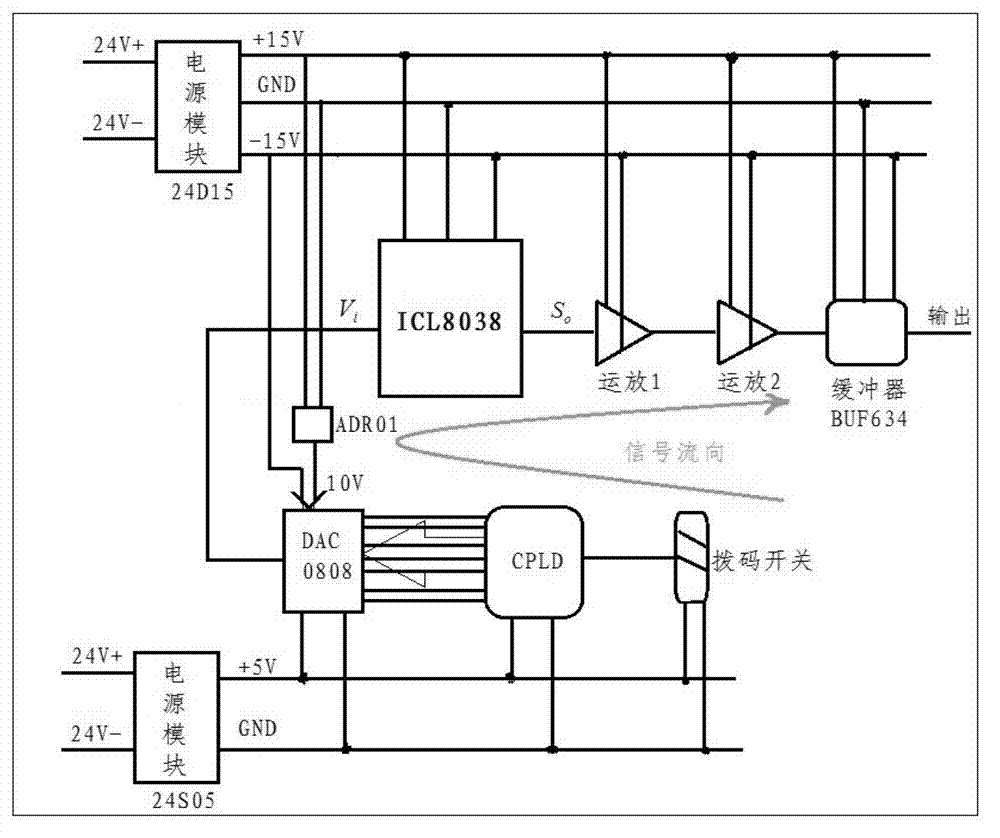
[0042] The object selected in this case is the resolver excitation circuit. The circuit is used to generate the sinusoidal signal required by the excitation winding of the resolver to provide excitation for the operation of the resolver, thereby realizing the detection requirements of the motor position in control systems such as aviation permanent magnet synchronous motors and brushless DC motors. The functional block diagram of the circuit is shown in figure 1 shown.

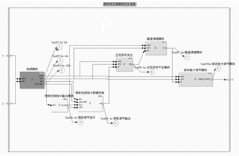
[0043] Based on the functional structure of the resolver excitation circuit, the testability modeling software is used to model the circuit, and the correlation model is obtained as follows: figure 2 As shown, the test model includes six functional modules including power supply module, sinusoidal signal generation, frequency control command digital-to-analog conversion, frequency control command output module, amplitude conditioning module, and drive capability adjustment module, and eight physical modules ...


PUM


Abstract

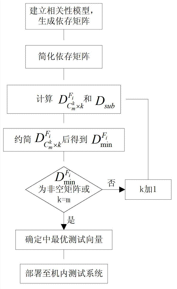
The invention belongs to the testability technology and relates to a built-in testing design method based on a relevance model. The method uses a product relevance model as a basis and comprises the following steps of: at first, simplifying the relevance model, and removing a redundancy test and combining an ambiguity group; secondly, identifying a minimum test vector matrix corresponding to each fault; thirdly, determining an optimal testing vector according to a reliability index and a test cost of a test as a criterion for fault detection and separation; and finally, converting the criterion into an embedded diagnostic program and arranging the embedded diagnostic program in a built-in test of a product. With the adoption of the method provided by the invention, a fault source can be accurately found out through the optimal test cost and the least test quantity, so that the testability and the design level of an electronic product can be improved.

Description

technical field [0001] The invention belongs to testing technology and relates to an in-machine test design method based on a correlation model. Background technique [0002] With the development and application of large-scale integrated circuits, the integration of electronic equipment is getting higher and higher, and the functions are becoming more and more complex, followed by the diversification of failure modes, which reflect strong coupling and correlation. When one type of fault occurs, it will cause multiple faults to occur at the same time, resulting in long and difficult fault detection and isolation time, and a rapid increase in maintenance workload. [0003] Built-in test (Built-in test, BIT) technology is the comprehensive ability of the system or equipment to rely on its internal detection circuit and detection software to complete system or equipment working parameter monitoring, fault detection and isolation. [0004] The existing BIT engineering design met...

Claims


Application Information

Patent Timeline
IPC IPC(8): G06F17/50
Inventor 李璠蒋觉义刘萌萌曾照洋
Owner CHINA AERO POLYTECH ESTAB
Learn More