Design method of guide-following edge reinforcement for composite propeller blades

A technology of composite materials and design methods, applied in computing, special data processing applications, instruments, etc., can solve problems such as damage to composite propeller blades, and achieve the goal of ensuring propulsion performance, improving impact resistance, and ensuring realizability Effect

Active Publication Date: 2017-02-08
HARBIN INST OF TECH
View PDF1 Cites 0 Cited by
  • Summary
  • Abstract
  • Description
  • Claims
  • Application Information

AI Technical Summary

Problems solved by technology

[0004] In order to solve the problem that the existing composite material propeller blades are easily damaged by the impact of external objects, the invention further proposes a design method for reinforcing the leading edge of the composite material propeller blades

Method used


Image

  • Design method of guide-following edge reinforcement for composite propeller blades
  • Design method of guide-following edge reinforcement for composite propeller blades
  • Design method of guide-following edge reinforcement for composite propeller blades

Examples


specific Embodiment approach 1

[0017] Specific implementation mode one: combine figure 1 , figure 2 with image 3 To illustrate this embodiment, the specific steps of the design method for leading and trailing edge reinforcement of a composite material propeller blade described in this embodiment are as follows:

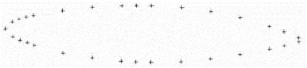
[0018] Step 1. Use the 3D solid configuration software to draw the geometric model of the blade section, and calculate that the distance from the leading edge on the nR section is 0.05C chord The ordinate values ​​of leaf surface and leaf back, where n=0.1,0.2,…0.9,1, C chord is the chord length of the nR section, and R represents the radius of the propeller;

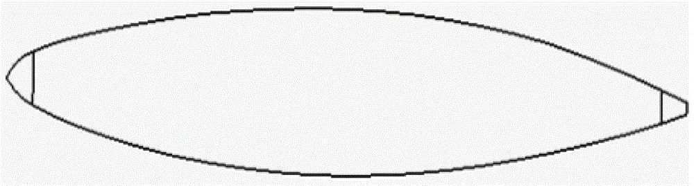
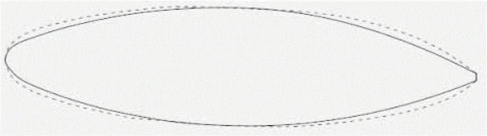
[0019] Step 2, the HLA of each section nr 、HLB nr 、HTA nr and HTB nr The value is increased by m times, and according to these ordinate values, use mathematical modeling software to refit and adjust the remaining model value points of the nRth section to construct a new section form of the propeller blade, where HLA nr Indicates th...

specific Embodiment approach 2

[0028] Specific implementation mode two: combination figure 1 , figure 2 with image 3 Describe the present embodiment, the design method of the leading edge reinforcement of the composite material propeller blade described in the present embodiment, it is characterized in that: the derivation process of formula (1) in the step 5 is as follows:

[0029] Step A, propeller blades rotate in viscous turbulent flow, the continuity equation and the momentum equation of RANS are:

[0030] Continuity equation: ∂ ρ ∂ t ( ρu i ) + ∂ ∂ x i ( ρu i ) = 0 - - - ( 2 ) ,

[0031] Momentum equation: ∂ ∂...

specific Embodiment approach 3

[0042] Specific implementation mode three: combination figure 1 , figure 2 with image 3 To illustrate this embodiment, m=1.05, 1.1, 1.15, 1.2 in step 2 of the leading edge reinforcement design method for a composite propeller blade described in this embodiment. Other components and connections are the same as those in the first embodiment.


PUM


Abstract

The invention relates to a design method for processing a guide following edge, in particular to the design method for reinforcing the guide following edge of a compound propeller blade, and aims to solve the problem that the conventional compound propeller blade is easily damaged when being impacted by an external object. The design method comprises the following steps: drawing a geometrical model of the cross section of the blade and a geometrical model of the blade by utilizing a three-dimensional configuration software; calculating the hydrodynamic performance of the blade by utilizing an RANS (Reynolds-Averaged Navier-Stokes) equation; selecting i types of improvement schemes meeting the requirement of the hydrodynamic performance according to the hydrodynamic performance of the blade; estimating the volume of the propeller according to the finally determined geometrical model, and further estimating the weight G of the propeller; and determining the improvement scheme of the minimal weight G as a design scheme for the guide following edge reinforced compound propeller blade. The design method is applied to transportation tools such as naval vessels.

Description

technical field [0001] The invention relates to a leading edge processing design method, in particular to a leading edge reinforcement design method of a composite material propeller blade. Background technique [0002] In recent years, with the wide application of fiber-reinforced composite materials, more and more designers have begun to use lightweight composite materials to replace relatively heavy metal materials to prepare propeller blades. Compared with traditional metal propellers, composite propellers have The characteristics of light weight, high efficiency, low vibration, low noise, seawater corrosion resistance and easy maintenance have solved the problems of heavy metal propellers in the past, difficult processing, serious cavitation corrosion, and large vibration and noise. There is also a special problem with lightweight composite propellers: the blades are easily damaged by the impact of external objects, especially for the leading and trailing edge parts of ...

Claims


Application Information

Patent Timeline
Patent Type & Authority Patents(China)
IPC IPC(8): G06F17/50
Inventor 赫晓东洪毅王荣国刘文博杨帆矫维成郝立峰徐忠海张鸿名
Owner HARBIN INST OF TECH
Why Eureka
Try Eureka