Meshing-area-adjusting type synchronous magnetic torque converter and speed regulation method thereof
An adjustable meshing area technology, which is applied in the direction of electrical components, electromechanical devices, electromechanical transmissions, etc., can solve the problems of motor heating and failure, and achieve the effects of improved transmission efficiency, accurate meshing area, and precise size control
- Summary
- Abstract
- Description
- Claims
- Application Information
AI Technical Summary
Problems solved by technology
Method used
Image
Examples
Embodiment 1
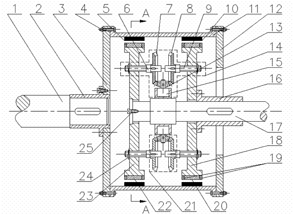
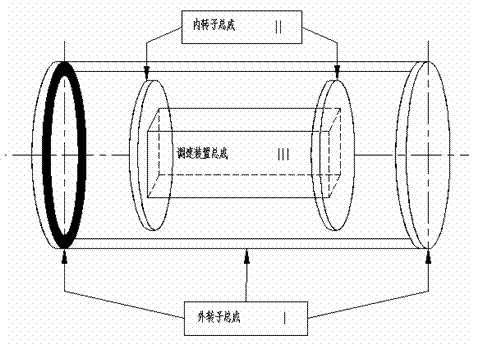
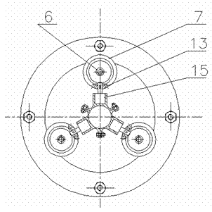
[0032] The working principle of Embodiment 1: When the driving shaft 1 is driven by the motor to rotate, it drives the outer rotor base 11 to rotate. Since the left permanent magnet 5 and the right permanent magnet 10 are glued on the outer rotor base 11, a rotating magnetic field is formed, and the magnetic coupling The left copper bar 22 on the inner rotor left base body 23 and the right copper bar 20 on the inner rotor right base body 18 produce induced eddy currents on the left copper bar 22 and the right copper bar 20 due to cutting the magnetic force lines of the permanent magnet, and the magnetic field of the eddy current and The magnetic field interaction of the permanent magnets makes the left and right bases 23, 18 of the inner rotor rotate.
[0033] The principle of speed regulation in Embodiment 1: When the speed difference between the inner and outer rotors of the magnetic coupler is constant, the power transmission capacity between the inner and outer rotors of th...
PUM
 Abstract
Description
Claims
Application Information
 - R&D
- Intellectual Property
- Life Sciences
- Materials
- Tech Scout
- Unparalleled Data Quality
- Higher Quality Content
- 60% Fewer Hallucinations
Browse by: Latest US Patents, China's latest patents, Technical Efficacy Thesaurus, Application Domain, Technology Topic, Popular Technical Reports.
© 2025 PatSnap. All rights reserved.Legal|Privacy policy|Modern Slavery Act Transparency Statement|Sitemap|About US| Contact US: help@patsnap.com


