Nanoflotation

A flotation box and foam flotation technology, applied in the field of nano-flotation, can solve the problems of rough membrane and membrane interval and the effect of pre-coating, etc.

Active Publication Date: 2013-02-13
643096 ALBERTA
View PDF7 Cites 6 Cited by
  • Summary
  • Abstract
  • Description
  • Claims
  • Application Information

AI Technical Summary

Problems solved by technology

[0007] The benefits of froth flotation with submerged membranes are discussed in journal papers by Lazaridis et al. (Aristotle University, Greece), June 2003 and June 2004, However, the effect of using rough membranes and membrane spacing and pre-coating in combination with froth flotation was not explored

Method used


Image

  • Nanoflotation
  • Nanoflotation
  • Nanoflotation

Examples


Embodiment Construction

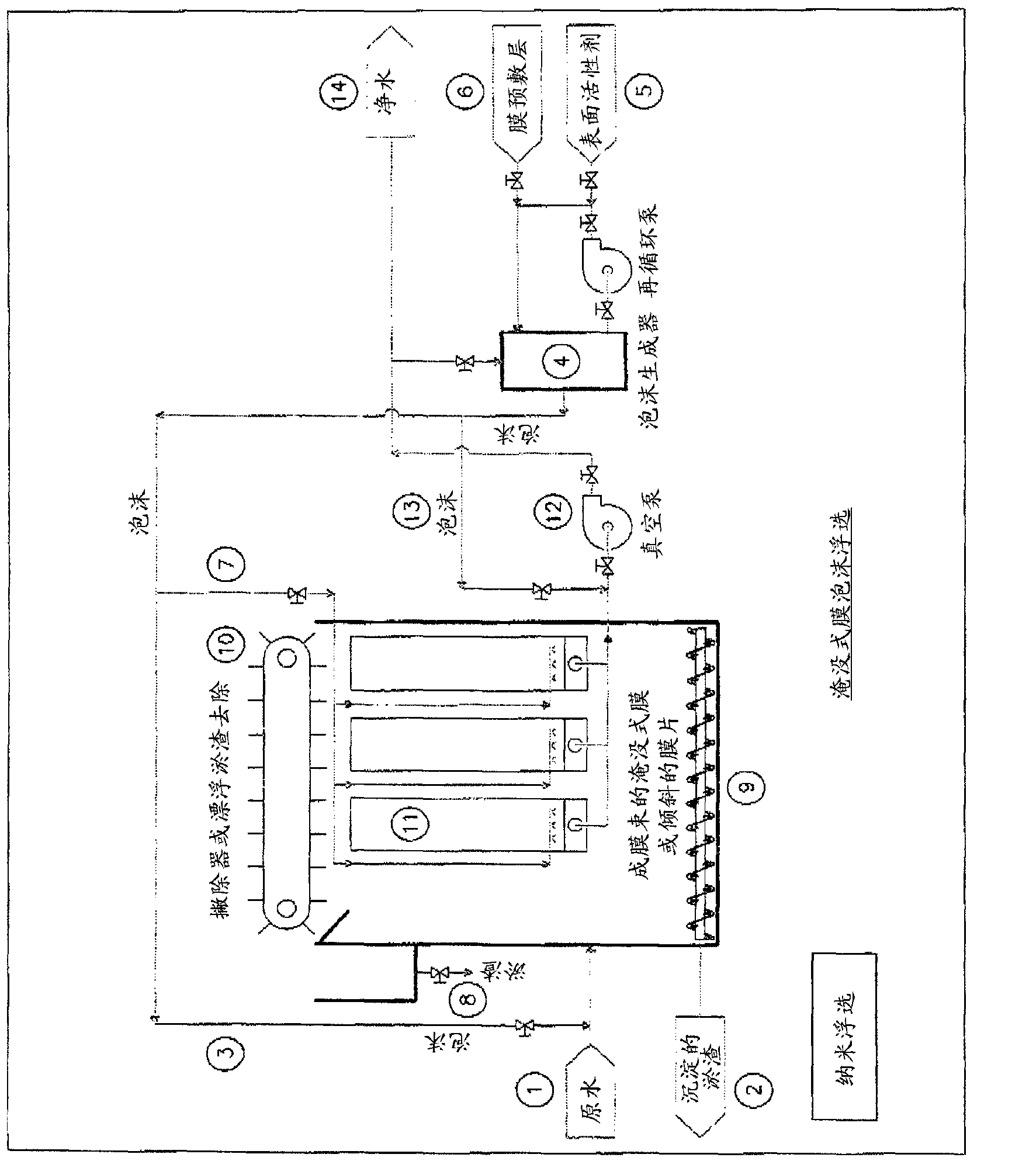
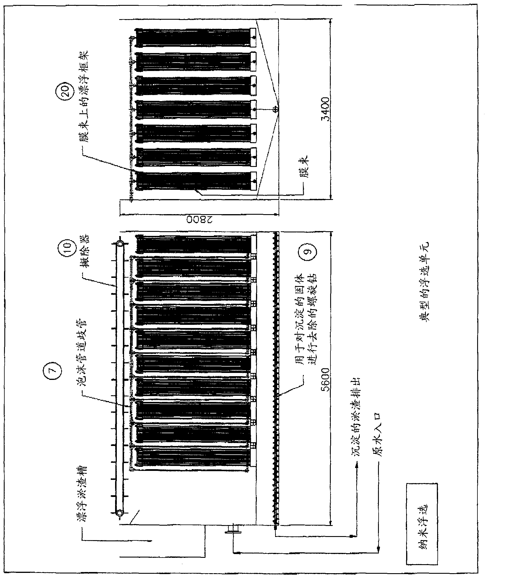
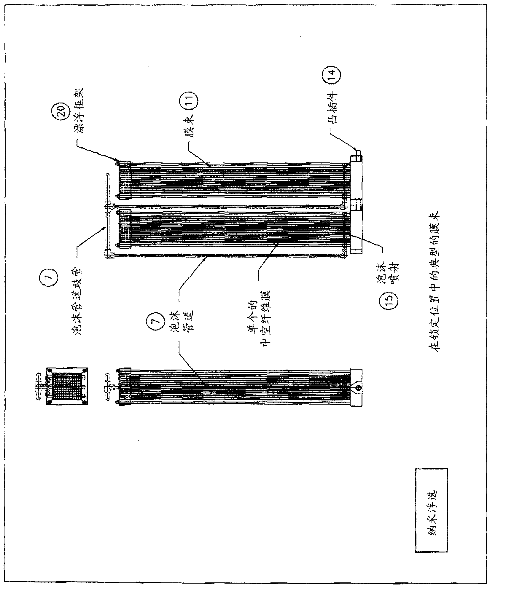
[0025] Raw water or waste water or any liquid 1 requiring solids separation is conveyed to a flotation tank or flotation cell which has an area on the bottom 9 for the settled solids and an area on the top for With an area where the flotation solids are collected or a skim or floating layer 10, the flotation cell or flotation cell has means to remove solids from both the top and the bottom. The flotation tank / unit will comprise submerged membranes 11,23. Sludge is removed from the flotation tank / unit via the bottom of the tank / unit and / or the skimming collection tank 8 . Water or waste water or any liquid 1 with solids entering the flotation cell / tank has froth 3 added to the water or waste water or liquid 1 with solids. Foam is generated from a typical foam generator 4 . The foam is formed by using a foam 5-forming surfactant or the like. Foam is also added between the membrane fibers 16 or flat sheets 23 during normal filtration operation of the flotation cell / unit. The ...


PUM


Abstract

A nanoflotation system used to separate suspended solids or large settling or floating solids from water, waste water or liquids. This is accomplished through the use of submerged membranes,ll,23, in combination with five design components; froth flotation, 4, gravity settling,9, pre coating of the submerged membranes,6, spacing, figure 4,of the membranes to facilitate flotation of solids to the surface or to the bottom of the containment chamber holding the submerged membranes, and membrane structures which use large diameter hollow fibre or tubular membranes and / or large pore opening membrane materials.

Description

technical field [0001] Water and wastewater treatment, solid and liquid recovery. Background technique [0002] The application of submerged membranes has made many achievements. A key issue is membrane fouling and membrane maintenance. Many inventions have used air to reduce membrane fouling. In addition, there are traditional methods of separating solids from liquids. This traditional method uses a clarifier with or without settling tubes or inclined settling plates, or an air flotation system in which high pressure dissolved air is used, or an induced air or froth flotation system to separate the solids and float the solids to the surface and then remove the solid sludge / skim layer with a skimmer or skim / float separation system. [0003] The present invention uses all of these components but focuses on the use of a pre-coating of nanoparticles on rough (large pore and large diameter) submerged membranes and on the use of froth flotation and membrane spacing to enhance...

Claims


Application Information

Patent Timeline
Patent Type & Authority Applications(China)
IPC IPC(8): B01D65/08B01D65/02B01D69/08C02F1/00C02F1/24C02F1/44
CPCB01D2313/26B01D2315/06C02F1/44B03D1/1481B01D63/024C02F2303/16B03D1/1475B01D2311/26C02F1/442B01D2313/08B03D1/1462B01D69/08B01D63/02B01D61/18B01D61/20B01D63/08C02F2303/20B03D1/1468B03D1/247C02F1/24B01D2315/18
Inventor 大卫·布罗姆利
Owner 643096 ALBERTA
Why Eureka
Try Eureka