
Biomass pyrolysis combustion furnace

A biomass pyrolysis and combustion furnace technology, which is applied in the field of biomass pyrolysis and combustion, biomass pyrolysis combustion furnace, can solve the problem of unfavorable recycling of waste and residue, insufficient combustion of materials, insufficient combustion or pyrolysis, etc. problem, to achieve the effect of complete pyrolysis, complete combustion and full utilization

Inactive Publication Date: 2013-02-27
CHENGDU WANGAN IND
View PDF4 Cites 4 Cited by
  • Summary
  • Abstract
  • Description
  • Claims
  • Application Information

AI Technical Summary

Problems solved by technology

[0005] Since the above-mentioned technical scheme is that there are a plurality of air outlet holes evenly distributed on the side of the lower part of the inner tank, it can achieve the purpose of supplementing the materials in the inner tank with oxygen when burning, but the materials in the upper part of the inner tank are very difficult to burn during the combustion process. Poor access to oxygen, resulting in insufficient combustion or pyrolysis
Moreover, only relying on the evenly distributed small holes at the bottom of the inner tank cannot meet the oxygen required for combustion.
Therefore, this patented technical solution still exists, the pyrolysis is insufficient, the defect that the material cannot be fully burned, and there are also wastes and residues that are not conducive to recycling.

Method used


Image

  • Biomass pyrolysis combustion furnace
  • Biomass pyrolysis combustion furnace
  • Biomass pyrolysis combustion furnace

Examples


Embodiment 1

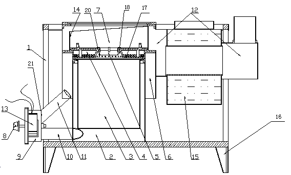
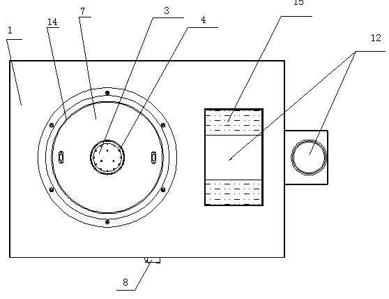
[0049] A biomass pyrolysis combustion furnace, comprising a bracket, a furnace shell, an air inlet and a wind cap arranged on the furnace shell, the furnace shell is arranged on the support, the furnace shell is located in the furnace shell, and the air inlet is arranged on the furnace shell, It is characterized in that: the air cap has an upper and lower structure and forms a secondary air supply chamber, and a truncated conical ignition cavity is arranged axially in the middle, the bottom of the furnace has holes, and a gap is arranged between the bottom of the furnace and the furnace shell. The primary air supply chamber and the air inlet are respectively connected to the primary air supply chamber and the secondary air supply chamber, and a combustion chamber is formed between the wind cap and the upper inner wall of the furnace shell.

[0050] In the above embodiment, the materials in the furnace are ignited first, and then the hood is covered, so that the materials in the...

Embodiment 2

[0052]A biomass pyrolysis combustion furnace, comprising a bracket, a furnace shell, an air inlet and a wind cap arranged on the furnace shell, the furnace shell is arranged on the support, the furnace shell is located in the furnace shell, and the air inlet is arranged on the furnace shell, It is characterized in that: the air cap has an upper and lower structure and forms a secondary air supply chamber, and a truncated conical ignition cavity is arranged axially in the middle, the bottom of the furnace has holes, and a gap is arranged between the bottom of the furnace and the furnace shell. The primary air supply chamber and the air inlet are respectively connected to the primary air supply chamber and the secondary air supply chamber, and a combustion chamber is formed between the wind cap and the upper inner wall of the furnace shell. A layer of the wind cap close to the furnace is provided with pre-combustion air supply holes.

Embodiment 3

[0054] A biomass pyrolysis combustion furnace, comprising a bracket, a furnace shell, an air inlet and a wind cap arranged on the furnace shell, the furnace shell is arranged on the support, the furnace shell is located in the furnace shell, and the air inlet is arranged on the furnace shell, It is characterized in that: the air cap has an upper and lower structure and forms a secondary air supply chamber, and a truncated conical ignition cavity is arranged axially in the middle, the bottom of the furnace has holes, and a gap is arranged between the bottom of the furnace and the furnace shell. The primary air supply chamber and the air inlet are respectively connected to the primary air supply chamber and the secondary air supply chamber, and a combustion chamber is formed between the wind cap and the upper inner wall of the furnace shell. The side wall of the ignition chamber is provided with a secondary air supply hole communicating with the secondary air supply chamber.


PUM


Abstract

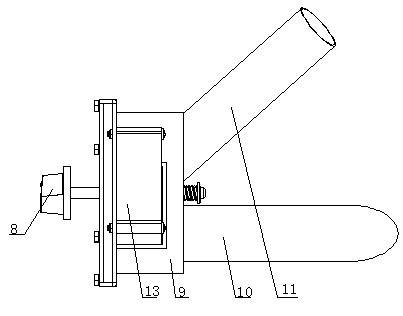
The invention discloses a biomass pyrolysis combustion furnace, and belongs to the filed of biomass fuel pyrolysis equipment. The biomass pyrolysis combustion furnace comprises a bracket, a furnace shell, air inlets and a funnel cap arranged on a furnace pipe, wherein the furnace shell is arranged on the bracket, the furnace pipe is located inside the furnace shell, the air inlet are formed on the furnace shell, the funnel cap is of a structure with an upper layer and a lower layer which form a secondary air supply chamber, a cone-frustum-shaped ignition cavity is arranged on the middle of the funnel cap in the axial direction, the bottom of the furnace pipe is provided with a hole, a primary air supply chamber is arranged between the bottom of the furnace pipe and the furnace shell, the air inlets are respectively connected to the primary air supply chamber and the secondary air supply chamber, and a combustion chamber is formed between the funnel cap and the inner wall of the upper part of the furnace shell. The biomass pyrolysis combustion furnace disclosed by the invention has the advantages that the pyrolysis of a biomass fuel is sufficient, the combustion is complete, and the heat energy after combustion is utilized fully.

Description

technical field [0001] The invention discloses a biomass pyrolysis combustion furnace, which belongs to the field of biomass fuel pyrolysis equipment. Especially suitable for pyrolysis and combustion of biomass. Background technique [0002] At present, the combustion furnaces used for biomass combustion on the market have become more popular, and the common principle is to firstly pyrolyze the biomass and burn the gas generated by the pyrolysis. However, there are defects such as insufficient biomass pyrolysis, long pyrolysis time, uneven pyrolysis, and low efficiency. [0003] Then there was a utility model titled multifunctional pyrolysis furnace for agricultural waste, and the application number was 201110006886, which was an invention patent with application date: January 10, 2011, and publication date: July 18, 2012. [0004] The technical scheme of the patented technology is as follows: including: an inner container, an outer cylinder arranged outside the inner cont...

Claims


Application Information

Patent Timeline
Patent Type & Authority Applications(China)
IPC IPC(8): F23B90/06
Inventor 王竹宏
Owner CHENGDU WANGAN IND
Learn More