Testing method for shielding effectiveness of small-size shielding cavity

A technology of shielding effectiveness and test method, applied in the direction of measuring electricity, measuring device, measuring electrical variables, etc., can solve the problems of receiving test, large size, and inability to place the antenna inside the cavity, and achieves good versatility, accuracy and Effects with high dynamic range

Inactive Publication Date: 2013-02-27
XIAN KAIRONG ELECTRONICS TECH
View PDF8 Cites 31 Cited by
  • Summary
  • Abstract
  • Description
  • Claims
  • Application Information

AI Technical Summary

Problems solved by technology

[0002] In recent years, in the field of electromagnetic compatibility, the requirements for the anti-electromagnetic interference performance of products have become higher and higher. Since the electromagnetic interference radiation frequency bands of various electronic products are becoming wider and wider, and the low-frequency bands are particularly dense, this makes the anti-electromagnetic interference capabilities of products The requirements are becoming more and more stringent, and the ability to resist electromagnetic interference in the space often depends on the shielding effectiveness of the equipment cavity itself. Due to the development of modern electronic equipment towards miniaturization, the volume of the equipment is gradually redu

Method used


Image

  • Testing method for shielding effectiveness of small-size shielding cavity
  • Testing method for shielding effectiveness of small-size shielding cavity
  • Testing method for shielding effectiveness of small-size shielding cavity

Examples


Embodiment 1

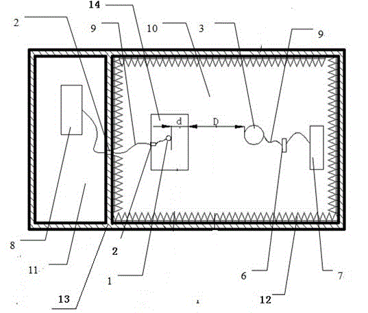
[0028] Such as figure 1 and figure 2 As shown, the semi-anechoic chamber is set up to prevent the incident signal from directly interfering with the receiver, and is an isolation environment adopted to avoid affecting the authenticity of the test.

[0029] The metal wall plate 13 divides the semi-anechoic chamber into two parts, namely the shielded darkroom 10 and the shielded chamber 11 , and the wave-absorbing material 12 is arranged on the wall of the shielded darkroom 10 .

[0030] The wave-absorbing material 12 is a wedge-shaped absorber of polyurethane foam type, non-woven flame-retardant type or silicate plate metal film assembly type.

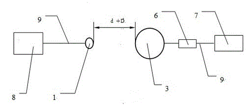
[0031] The metal wall plate 13 is provided with a two-way radio frequency connector 2, and the two ends of the two-way radio frequency connector 2 are respectively in the shielded dark room 10 and the shielded room 11, and the receiver 8 is placed inside the shielded room 11 alone.

[0032] The two-way radio frequency connector 2 is ...

Embodiment 2

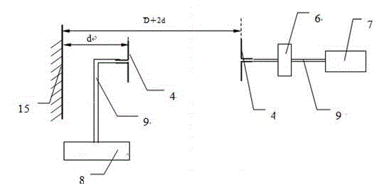
[0047] Such as image 3 and Figure 4 As shown, the equipment setup and test steps of this embodiment are exactly the same as those of Embodiment 1. The difference is that the near-field test antenna 1 and the transmitting antenna 3 use a half-wave vibrator antenna 4, which can perform shielding performance for the electric field frequency band from 100MHz to 1GHz. detection.

Embodiment 3

[0049] Such as Figure 5 and Figure 6 As shown, the equipment setup and test steps of the embodiment are exactly the same as those of the embodiment 1, the difference is that the near-field test antenna 1 and the transmitting antenna 3 adopt the microwave horn antenna 5, which can detect the shielding effectiveness for the plane wave frequency band from 1 GHz to 40 GHz .


PUM

PropertyMeasurementUnit
Diameteraaaaaaaaaa

Abstract

The invention discloses a testing method for the shielding effectiveness of a small-size shielding cavity. The testing method is characterized in that a shielding anechoic chamber and a shielding chamber are two cavities formed by separation through a metal wall plate; a wave absorbing material is arranged on the wall surface of the shielding anechoic chamber; the shielding anechoic chamber and the shielding chamber are independently grounded; a receiver is arranged in the shielding chamber; other devices are arranged in the shielding anechoic chamber; a bidirectional radio frequency connector is arranged on the wall surface of the metal wall plate; a near-field test antenna is arranged in the shielding anechoic chamber and is sequentially conducted with the bidirectional radio frequency connector and the receiver which are arranged on the wall surface of the metal wall plate through a coaxial cable; a transmitting antenna is sequentially conducted with a pre-amplifier and a signal source through a coaxial cable; the transmitting antenna, the pre-amplifier and the signal source are arranged in the shielding chamber; the center of the transmitting antenna corresponds to the center of the near-field test antenna; and the testing method is realized by three steps of measuring a direct-connection receiving value and a radio frequency leakage quantity and calculating the shielding effectiveness. The testing method is simple and accurate.

Description

technical field [0001] The invention relates to the technical field of electronic testing and shielding effectiveness testing, and relates to a method for testing the shielding effectiveness of a small shielding cavity. Background technique [0002] In recent years, in the field of electromagnetic compatibility, the requirements for the anti-electromagnetic interference performance of products have become higher and higher. Since the electromagnetic interference radiation frequency bands of various electronic products are becoming wider and wider, and the low-frequency bands are particularly dense, this makes the anti-electromagnetic interference capabilities of products The requirements are becoming more and more stringent, and the ability to resist electromagnetic interference in the space often depends on the shielding effectiveness of the equipment cavity itself. Due to the development of modern electronic equipment towards miniaturization, the volume of the equipment is ...

Claims


Application Information

Patent Timeline
IPC IPC(8): G01R31/00G01R29/08
Inventor 宋博
Owner XIAN KAIRONG ELECTRONICS TECH
Why Eureka
Try Eureka