High-gain interleaving boost converter

A boost converter, high-gain technology, applied in the direction of conversion equipment without intermediate conversion to AC, can solve the problems of large voltage stress of switch tubes and diodes, too many switching devices, and reduced energy conversion efficiency, and achieve low EMI , The circuit topology is simple, and the effect of reducing voltage stress

Active Publication Date: 2013-02-27
CHONGQING UNIV
View PDF4 Cites 36 Cited by
  • Summary
  • Abstract
  • Description
  • Claims
  • Application Information

AI Technical Summary

Problems solved by technology

[0005] Aiming at the above-mentioned deficiencies in the prior art, the present invention solves the problems of lower energy conversion efficiency, too many switching devic

Method used


Image

  • High-gain interleaving boost converter
  • High-gain interleaving boost converter
  • High-gain interleaving boost converter

Examples


Example Embodiment

[0022] The present invention will be further described in detail below with reference to the drawings and specific embodiments.

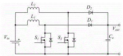
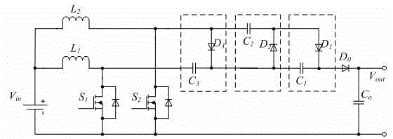
[0023] Such as figure 2 As shown, an interleaved parallel boost converter with high gain capability includes a low-voltage input power supply and a DC / DC boost circuit; the high gain interleaved parallel DC-DC converter includes two inductors L 1 , L 2 , Two power switches S 1 , S 2 , An output diode D 0 And 3 voltage doubling units (consisting of 3 diodes and 3 capacitors);

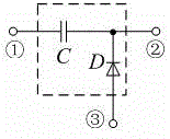
[0024] Such as image 3 As shown, the voltage doubler unit is composed of a diode and a capacitor to form a unit with three ports. The first port is connected to one end of the capacitor, the node between the other end of the capacitor and the cathode of the diode serves as the second port, and the anode end of the diode serves as the third port .

[0025] The first inductance L 1 The input terminal is connected to the positive terminal of the input power supply, and the output ter...


PUM


Abstract

The invention provides a high-gain interleaving boost converter. The high-gain interleaving boost converter comprises two inductors, two power switches, an output diode and voltage-multiplying units, wherein the voltage-multiplying units form a three-port unit by a diode and a capacitor; the first port is connected with one end of the capacitor, the other end of the capacitor and the node of the diode cathode are used as the second port; and the anode of the diode is used as the third port. The base gain is doubled on the basis of the gain of the original circuit by adding one voltage-multiplying unit in the circuit each time, i.e. the gain ratio of the circuit is (n+1) times that of the base boost converter by adding n voltage-multiplying units in the circuit. Compared with the conventional high-gain boost converters, the high-gain interleaving boost converter disclosed by the invention has simple circuit topology and no coupling inductance (EMI (Electro-Magnetic Interference) small), and can greatly reduce voltage stress of a switching element, so that the integral working efficiency of the converter is improved.

Description

technical field [0001] The invention relates to a DC-DC converter, in particular to a high-gain interleaved parallel boost converter. [0002] Background technique [0003] In the prior art, the basic step-up (Boost) interleaved parallel converter, see appendix figure 1 (Take two-phase interleaved parallel connection as an example), it includes two inductors, two power switch tubes, and two output diodes. Among them, the input terminal of the first inductor and the input terminal of the second inductor are connected to the positive pole of the input power supply, the output terminal is connected to the anode of the first output diode, and the cathode of the first diode is connected to the cathode of the second diode together. The positive pole of the output terminal of the converter; the drain of the first power switch is connected between the first inductor and the anode of the first diode, and the source of the first power switch is connected to the negative pole of the ...

Claims


Application Information

Patent Timeline
IPC IPC(8): H02M3/07
Inventor 罗全明邾玢鑫周雒维孙鹏菊
Owner CHONGQING UNIV
Why Eureka
Try Eureka