Uplink power control method of multiple-antenna system, and user terminal

A multi-antenna system and power control technology, applied in power management, wireless communication, sustainable buildings, etc., can solve the problems of system performance degradation, inability to achieve fast adjustment, matching, etc.

Inactive Publication Date: 2013-02-27
ZTE CORP
View PDF4 Cites 7 Cited by
  • Summary
  • Abstract
  • Description
  • Claims
  • Application Information

AI Technical Summary

Problems solved by technology

Therefore, the eNB cannot achieve the purpose of quickly adjusting the UE to transmit PSD through the MCS allocated to the UE
[0048] Moreover, when the wireless channel environment changes drastically, and one of the uplink dual-codeword streams or the MCS level of the uplink dual-codeword stream changes greatly within a time interval of the durati

Method used


Image

  • Uplink power control method of multiple-antenna system, and user terminal
  • Uplink power control method of multiple-antenna system, and user terminal
  • Uplink power control method of multiple-antenna system, and user terminal

Examples


Embodiment 1

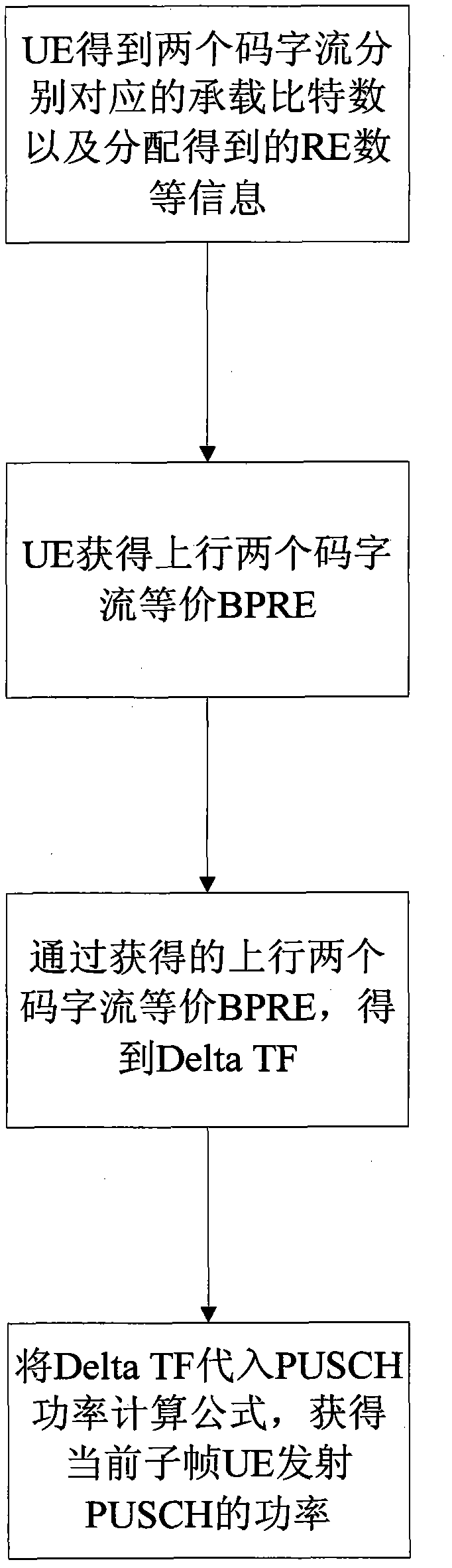
[0156] Suppose that in subframe i, the UE is configured with uplink dual codeword stream transmission, the first codeword stream is CW0, and the second codeword stream is CW1, and all user data is carried.

[0157] Assume that the number of user data coding blocks on CW0 is C (0) , Where the coding block size of the m-th coding block is The number of user data coding blocks on CW1 is C (1) , Where the coding block size of the m-th coding block is

[0158] Assuming that the number of REs allocated during the initial transmission of CW0 is The number of RE allocated during the initial transmission of CW1 is

[0159] Then the UE calculates the equivalent BPRE of the UE uplink dual codeword stream at time i according to the following formula:

[0160] BPRE = X r = 0 C ( 0 ) - 1 K r ( 0 ) + X r = 0 C ( 1 ) - 1 K r ( 1 ) N RE ( 0 ) + N RE ( 1 )

[0161] The...

Embodiment 2

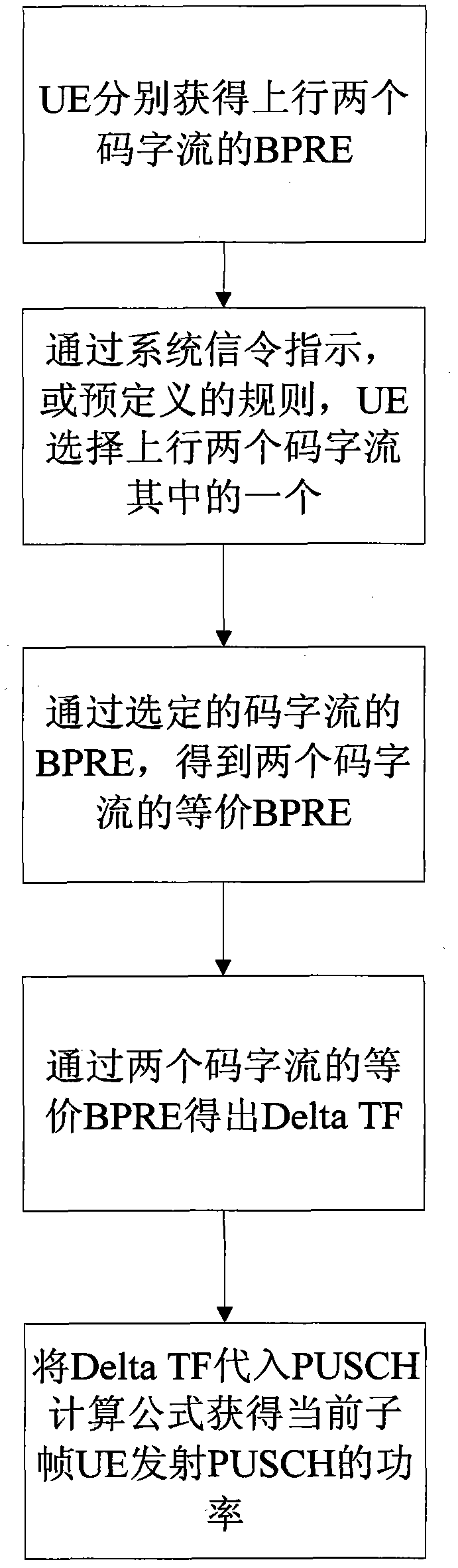
[0168] Assuming that in subframe i, the UE is configured with uplink dual codeword stream transmission, the first codeword stream is CW0, the second codeword stream is CW1, and all uplink control information is carried.

[0169] Assume that the number of uplink control signal data bits on CW0 is Suppose the number of uplink control signal data bits on CW1 is

[0170] Assuming that the number of REs allocated during the initial transmission of CW0 is The number of RE allocated during the initial transmission of CW1 is

[0171] Then the UE calculates the equivalent BPRE of the dual codeword stream of subframe i according to the following formula:

[0172] BPRE = O CQI ( 0 ) + O CQI ( 1 ) N RE ( 0 ) + N RE ( 1 )

[0173] Then, according to the method in Embodiment 1, the uplink power of the UE transmitting the PUSCH in the subframe i is calculated.

Embodiment 3

[0175] Assuming that in subframe i, the UE is configured with uplink dual codeword stream transmission, the first codeword stream is CW0, and the second codeword stream is CW1, where CW0 carries uplink control information, and CW1 carries user uplink data.

[0176] Assume that the number of uplink control signal data bits on CW0 is The number of user data coding blocks on CW1 is C (1) , Where the coding block size of the m-th coding block is

[0177] Assuming that the number of REs allocated during the initial transmission of CW0 is The number of RE allocated during the initial transmission of CW1 is

[0178] Then the UE calculates the equivalent BPRE of the dual codeword stream of subframe i according to the following formula:

[0179] BPRE = O CQI ( 0 ) + X r = 0 C ( 1 ) - 1 K r ( 1 ) N RE ( 0 ) + N RE ( 1 )

[0180] Then, according to the method in Embodiment 1, the uplink pow...


PUM


Abstract

The invention discloses a power control method of a multiple-antenna system, and a user terminal, which can realize obtaining of Delta TF (Delta Transmission Format) parameters under an uplink dicode word flow of UE (user equipment). Through the Delta TF parameters, eNB (evolved Node B) can control the uplink PSD (Power Spectral Density) of the UE only by controlling the MCS (Modulation and Coding Scheme) of an uplink code word flow of the UE. The method provided by the invention has the advantage that the eNB can control the PSD of the UE more flexibly and effectively, so that the purposes of lowering system interference, ensuring transmission power of the UE and increasing system throughput can be achieved.

Description

Technical field [0001] The present invention relates to the field of digital communication, in particular to LTE (Long Term Evolution, 3GPP Long Term Evolution) and LTE-A (Long Term Evolution Advanced, 3GPP Long Term Evolution), and specifically to a power control method for a multi-antenna system And user terminal. Background technique [0002] LTE-A is an evolved version of LTE. Its purpose is to meet the higher demands and more applications of the wireless communication market in the next few years, and to meet and exceed the needs of IMT-Advanced (Intemational Mobile Telecommunications-Advanced, advanced international mobile communications). At the same time, it maintains better backward compatibility with LTE. [0003] In the LTE system, MIMO (Multiple-Input Multiple-Output) technology is introduced in order to improve the spectrum efficiency of the system. Multi-antenna units are used at both the transmitting and receiving ends of a wireless system. The multi-dimensional ch...

Claims


Application Information

Patent Timeline
IPC IPC(8): H04W52/14
CPCY02B60/50
Inventor 林志嵘任璐戴博夏树强陈东丽
Owner ZTE CORP
Why Eureka
Try Eureka