Supercharge Your Innovation With Domain-Expert AI Agents!

Double-row upright bottle blowing machine with turntable

A blow molding machine, vertical technology, applied in the field of double-row vertical turntable blow molding machines, can solve the problems of low efficiency, large floor space, large energy consumption, etc., to improve work efficiency, small floor space, and energy saving Effect

Inactive Publication Date: 2013-03-06
GUANGDONG LESHAN INTELLIGENT EQUIP CORP LTD
View PDF4 Cites 4 Cited by
  • Summary
  • Abstract
  • Description
  • Claims
  • Application Information

AI Technical Summary

Problems solved by technology

[0003] For example, the Chinese Patent Office announced a utility model titled: Automatic Plastic Stretch-Blow Molding Machine: the patent number is: 01232773.5, and its structure is: it has a frame, a tube blank conveying device, a feeding device, a steering insertion device, a heating device, The bottle unloading device, the conveying device has a fixed slide rail, and there is a through-groove annular slideway on the slideway. There are grippers that move along the slideway, and the driving wheels that push the gripper forward. The holder has a pulley matched with the slideway. There is a tube blank seat on the pulley, and the rotation sprocket at the lower end of the tube blank seat. The rotation sprocket meshes with the rotation chain driven by the sprocket. The above technology is a linear double-frame movement. This technology adopts reciprocating motion, which has low efficiency, high energy consumption, horizontal structure, and large floor space.

Method used


Image

  • Double-row upright bottle blowing machine with turntable
  • Double-row upright bottle blowing machine with turntable

Examples


Embodiment Construction

[0014] The present invention will be further described below in conjunction with accompanying drawing.

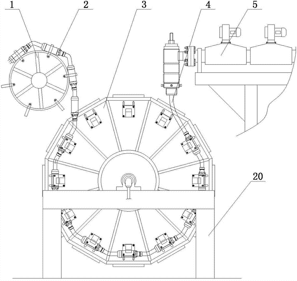
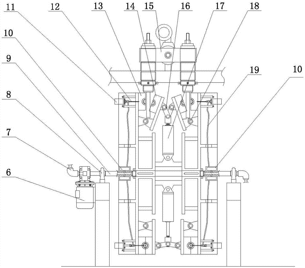
[0015] As shown in the figure, the double-row vertical turntable blow molding machine of the present invention includes a frame 20 provided with a rotating shaft 9, the frame 20 is provided with a bearing 8 with a seat, the rotating shaft 9 passes through the bearing 8 with a seat, and the rotating shaft 9 Run smoothly under the drive of geared motor 6. The rotating shaft 9 is connected to the fixed mold installation disk 3, and a mold is set on the fixed mold installation disk 3, and the fixed mold installation disk 3 is divided into two arrangements on the left and right, and several fixed molds 13 and The movable mold 14 and the fixed mold 13 are fixedly installed on the periphery of the fixed mold mounting plate 3, the blowing needle 12 faces the mold cavity, the movable mold 14 is actively connected to the fixed mold mounting plate 3 by the movable mold hinge 18, and i...


PUM


Abstract

The invention relates to the technical field of plastic bottle blowing equipment, and particularly belongs to a double-row upright bottle blowing machine with a turntable. The double-row upright bottle blowing machine comprises a framework with a rotary shaft, the rotary shaft is connected with a left fixed mold mounting plate and a right fixed mold mounting plate, molds are arranged on the fixed mold mounting plates, a plurality of fixed molds and a plurality of movable molds are mounted between the two fixed mold mounting plates, the fixed molds are mounted on corresponding one surfaces of the fixed mold mounting plates in pairs, each two corresponding movable molds are reversely movably connected to the fixed mold mounting plates by movable mold hinges, each two corresponding movable molds which are mounted between the fixed mold mounting plates are movably connected to a driver by mold closing hinges, the drivers are mold closing cylinders or crankshaft connecting rods, blowing needles are aligned with cavities of the fixed mold, air tubes are arranged on the blowing needles, air distributing sleeves are arranged at two ends of the rotary shaft, the air tubes are connected with the air distributing sleeves, an air guide channel and air guide joints are arranged in the rotary shaft, air guide holes are arranged on the surface of the rotary shaft, and inner cavities of the air distributing sleeves are communicated with the air guide holes. The double-row upright bottle blowing machine is small in occupied floor area, realizes an effect of saving a field, is high in production efficiency and is energy-saving.

Description

technical field [0001] The invention relates to the technical field of plastic bottle blowing equipment, in particular to a double-row vertical turntable blow molding machine which uses a set of power to realize the simultaneous opening and closing of double-row molds. Background technique [0002] Plastic raw materials such as HDPE, PP, LDPE, PETG and other plastic materials are used to process hollow containers such as beverage bottles and engine oil tanks. First, the plastic extruder is used to extrude the plastic to the die head to form a hollow tube blank, and then the mold is closed and air is injected to make it Form into a bottle shape, open the mold and take off the bottle after the plastic bottle cools down. [0003] For example, the Chinese Patent Office announced a utility model titled: Automatic Plastic Stretch-Blow Molding Machine: the patent number is: 01232773.5, and its structure is: it has a frame, a tube blank conveying device, a feeding device, a steering...

Claims


Application Information

Patent Timeline
IPC IPC(8): B29C49/38B29C49/48B29C49/56B29C49/60
Inventor 郭锡南
Owner GUANGDONG LESHAN INTELLIGENT EQUIP CORP LTD
Features
  • R&D
  • Intellectual Property
  • Life Sciences
  • Materials
  • Tech Scout
  • Unparalleled Data Quality
  • Higher Quality Content
  • 60% Fewer Hallucinations
Learn More