High-speed railway based aerodynamic aerotrain with simulated wings on lateral sides of aerotrain body
An aerodynamic suspension and high-speed railway technology, applied in the field of locomotives and carriages, can solve problems such as waste of resources, inability to change tracks of trains, and incomplete security measures, and achieve the effect of reducing pressure and simple structure
- Summary
- Abstract
- Description
- Claims
- Application Information
AI Technical Summary
Problems solved by technology
Method used
Image
Examples
Embodiment 1
[0038] See Figure 4 and Figure 5, the wing-like structure is mainly composed of a fixed base 4 of cuboid structure and a horizontal wing 1 fixed thereon; wherein, one side of the fixed base is connected with the horizontal wing, and the other side is installed on the side of the locomotive or carriage, fixed The horizontal length of the base is 1 meter, the width is 50 cm, the thickness of the fixed base is 65 mm, and the horizontal wing is at a 90-degree right angle to the fixed base; The distance from the locomotive or the bottom of the carriage is 60 cm.
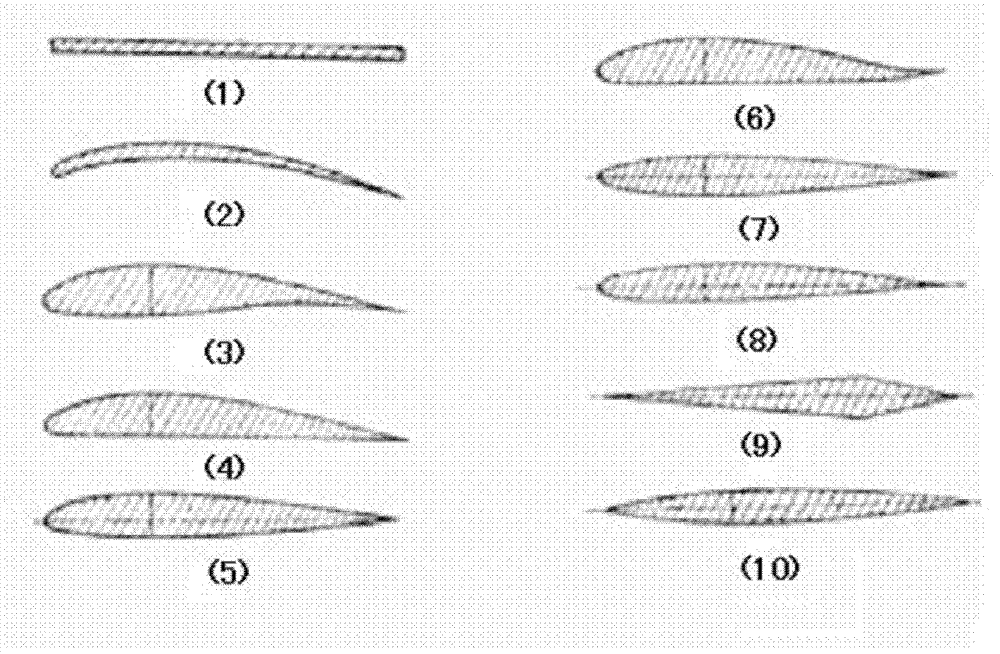
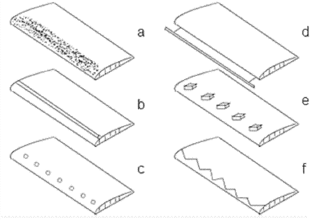
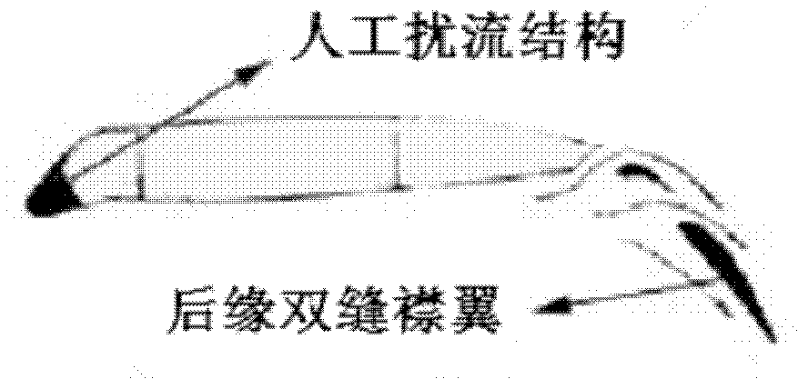
[0039] Described horizontal wing adopts flat wing, and the section of its flat wing is as follows figure 1 As shown in (1), it is streamlined as a whole, with an angle of attack, a leading edge sweep angle and a trailing edge sweep angle; the artificial spoiler structure 2 added near the leading edge part of the upper surface of the horizontal wing is A raised spoiler bar (such as figure 2 Shown in b); The trailin...
Embodiment 2
[0052] See Figure 4 and Figure 5 , the wing-like structure is mainly composed of a fixed base 4 of cuboid structure and a horizontal wing 1 fixed thereon; wherein, one side of the fixed base is connected with the horizontal wing, and the other side is installed on the side of the locomotive or carriage, fixed The horizontal length of the base is 1 meter, the width is 50 cm, the thickness of the fixed base is 60 mm, and the horizontal wing is at a 90-degree right angle to the fixed base; 70 cm from the bottom of the locomotive or carriage.
[0053] Described horizontal wing adopts flat wing, and the section of its flat wing is as follows figure 1 Shown in (1), the artificial spoiler structure added near the leading edge part of the upper surface of the horizontal wing is a zigzag protruding spoiler (such as figure 2 shown in f).
[0054] The area of described horizontal wing is 2.25 square meters, and this moment root tip ratio is 1, and the length of horizontal wing ...
Embodiment 3
[0066] See Figure 4 and Figure 5 , the wing-like structure is mainly composed of a fixed base 4 of cuboid structure and a horizontal wing 1 fixed thereon; wherein, one side of the fixed base is connected with the horizontal wing, and the other side is installed on the side of the locomotive or carriage, fixed The horizontal length of the base is 1 meter, the width is 50 cm, the thickness of the fixed base is 60 mm, and the horizontal wing is at a 90-degree right angle to the fixed base; 70 cm from the bottom of the locomotive or carriage.
[0067] Described horizontal wing adopts flat wing, and the section of its flat wing is as follows figure 1 Shown in (1), the artificial flow disturbance structure added near the leading edge part of the upper surface of the horizontal wing is to add an elastic flow-around band (such as figure 2 shown in d).
[0068] The area of described horizontal wing is 1.125 square meters, and this moment root tip ratio is 0.3, and the length ...
PUM
 Abstract
Description
Claims
Application Information
 - R&D
- Intellectual Property
- Life Sciences
- Materials
- Tech Scout
- Unparalleled Data Quality
- Higher Quality Content
- 60% Fewer Hallucinations
Browse by: Latest US Patents, China's latest patents, Technical Efficacy Thesaurus, Application Domain, Technology Topic, Popular Technical Reports.
© 2025 PatSnap. All rights reserved.Legal|Privacy policy|Modern Slavery Act Transparency Statement|Sitemap|About US| Contact US: help@patsnap.com


