
Demagnetizing method and device for steel wire lining conveyer belt by double magnetic rollers

A technology of degaussing device and degaussing method, applied in the direction of conveyors, transportation and packaging, magnetic objects, etc., can solve the problems of insufficient penetration, high density of steel wires on the conveyor belt, and failure to achieve degaussing effects, etc., to achieve simple structure, Easy implementation and obvious degaussing effect

Active Publication Date: 2013-03-06
BAOSHAN IRON & STEEL CO LTD
View PDF4 Cites 6 Cited by
  • Summary
  • Abstract
  • Description
  • Claims
  • Application Information

AI Technical Summary

Problems solved by technology

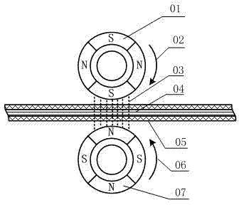
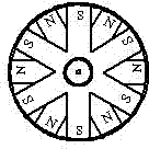
Chinese patent 200910053944.4 discloses a multi-pole magnetic roller asynchronous degaussing device for conveyor belts. The degaussing device adopts mechanical degaussing of multi-pole magnetic rollers. The main unsatisfactory points are: 1) The magnetic strength of the existing degaussing roller has reached the maximum value and cannot be further improved; 2) Due to the high density of steel wires in the conveyor belt, the existing single-sided degaussing roller "penetration "Not enough, so that the remanence index in the steel wire conveyor belt is often very high
Therefore, the steel wire lined conveyor belt can not achieve the best degaussing effect

Method used


Image

  • Demagnetizing method and device for steel wire lining conveyer belt by double magnetic rollers
  • Demagnetizing method and device for steel wire lining conveyer belt by double magnetic rollers
  • Demagnetizing method and device for steel wire lining conveyer belt by double magnetic rollers

Examples


Embodiment 1

[0040] see Figure 4 , Figure 5 , a steel wire lined conveyor belt double-roller degaussing device, comprising an upper degaussing roller 39, a lower degaussing roller 41, an upper degaussing roller drive pulley 24, a lower degaussing roller drive pulley 27, an upper degaussing roller rotating shaft bearing seat 25, a lower degaussing roller Roller shaft bearing seat 36, fixed bracket 30, motor power output pulley 22, belt guide pulley 26;

[0041] The upper degaussing roller rotating shaft 38 is set inside the upper degaussing roller 39, and the upper degaussing roller rotating shaft 38 is installed in the bearing housings 25 of the upper degaussing roller rotating shaft on both sides, and the bearing housings 25 are installed on the upper fixing bracket 30 through bolts 35. The fixed bracket 30 is installed on the frame 29 slotted hole 31 through the fixed bolt 32, and one end of the upper degaussing roller rotating shaft 38 is equipped with the upper degaussing roller dri...

Embodiment 2

[0051] see Image 6 , Figure 7 , a steel wire lined conveyor belt double-roller degaussing device, comprising an upper degaussing roller 57, a lower degaussing roller 60, an upper degaussing roller transmission gear 53, a lower degaussing roller transmission gear 54, an upper degaussing roller rotating shaft bearing seat 55, a lower degaussing roller Roller shaft bearing housing 58, motor power output gear 52;

[0052] The upper degaussing roller rotating shaft 56 is set in the upper degaussing roller 57, and the upper degaussing roller rotating shaft 56 is installed in the degaussing roller rotating shaft bearing housing 55 on both sides, and the bearing housing 55 is fixedly installed on the frame, and the upper degaussing roller rotating shaft One end of 56 is equipped with upper degaussing roller transmission gear 53;

[0053] The lower degaussing roller rotation shaft 59 is set inside the lower degaussing roller 60, and the lower degaussing roller rotation shaft 59 is ...


PUM


Abstract

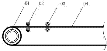
The invention relates to a demagnetizing method and device, and in particular relates to a demagnetizing method and device for a steel wire lining conveyer belt by double magnetic rollers. The demagnetizing method for the steel wire lining conveyer belt by double magnetic rollers comprises the steps of: placing two demagnetizing rollers (1 and 7) respectively above and below the steel wire lining conveyer belt (5), wherein the demagnetizing rollers are multiple-magnetic-pole magnetic rollers with adjacent heterospoles, and the diameters of the demagnetizing rollers are the same, the numbers of the magnetic poles are equal, and the magnetic densities are the same. The two demagnetizing rollers are synchronous at the same speed and rotate in opposite directions (2 and 6), and the heterospoles of the two demagnetizing rollers which rotate synchronously are opposite to each other; and the steel wire (4) lining conveyer belt moves. According to the demagnetizing method and device for the steel wire lining conveyer belt by the double magnetic rollers provided by the invention, the demagnetizing magnetic field is an alternating magnetic field which penetrates through the conveyer belt. The demagnetizing device provided by the invention is simple and compact in structure and easy to implement. Through field conduct and use, the lining steel wire of the demagnetized steel wire lining conveyer belt can be penetrated through more than 10mm, so that a demagnetizing effect is remarkable.

Description

technical field [0001] The invention relates to a degaussing method and device, in particular to a degaussing method and device for a steel wire-lined conveyor belt. Background technique [0002] The high-speed conveyor belt units of a certain enterprise all use super-strength steel wire-lined conveyor belts with a thickness of 26.1mm and a width of 1600mm. The diameter of each steel wire rope densely arranged in the conveyor belt reaches 8.1mm, and the conveyor belt carries heavy loads. It is one of the most advanced bulk ore transportation lines in the world. Due to the influence of the high-power electromagnet of the iron remover, the magnetization of the steel wire conveyor belt is very serious. Chinese patent 200910053944.4 discloses a multi-pole magnetic roller asynchronous degaussing device for conveyor belts. The degaussing device adopts mechanical degaussing of multi-pole magnetic rollers. The main unsatisfactory points are: 1) The magnetic strength of the...

Claims


Application Information

Patent Timeline
IPC IPC(8): H01F13/00B65G15/00
Inventor 孔利明李斌陈健丁海绍卢江海
Owner BAOSHAN IRON & STEEL CO LTD
Learn More