Maximum power tracking system and method of power transmission line induction power supply source

A technology of maximum power tracking and induction power acquisition, which is applied in electromagnetic wave systems, emergency power supply arrangements, circuit devices, etc., can solve problems such as limited battery life, heating of induction power extraction devices, and unsuitability for long-term work, so as to extend the design life. Effect of reducing time to feed

Inactive Publication Date: 2013-03-06
国网山东省电力公司聊城供电公司 +2
View PDF5 Cites 16 Cited by
  • Summary
  • Abstract
  • Description
  • Claims
  • Application Information

AI Technical Summary

Problems solved by technology

[0003] The application number is 200410061314.9, and the title of the invention is the patent document of induction power collection device for overhead high-voltage transmission lines. It uses the principle of current transformer to obtain electric energy from high-voltage transmission lines, but the technical solution in this document does not give the transmission line load. The effective output power of the current in its entire working range, especially the output power when the transmission line is no-load. In addition, when the load current of the transmission line is large, the induction power-taking device will heat up seriously
The application number is 200820066665.2, and the invention name is the patent document of high-voltage line induction power-taking device, which also uses the transformer principle to take power from the transmission line. The index given is that the output power when the load current of the transmission line is 80A-300A is 20-110W, but when the transmission line is no-load, the wire current is only about

Method used


Image

  • Maximum power tracking system and method of power transmission line induction power supply source
  • Maximum power tracking system and method of power transmission line induction power supply source
  • Maximum power tracking system and method of power transmission line induction power supply source

Examples


Embodiment Construction

[0031] In order to make the technical content disclosed in this application more detailed and complete, reference may be made to the drawings and the following various specific embodiments of the present invention, and the same symbols in the drawings represent the same or similar components. However, those skilled in the art should understand that the examples provided below are not intended to limit the scope of the present invention. In addition, the drawings are only for schematic illustration and are not drawn according to their original scale.

[0032] The specific implementation manners of various aspects of the present invention will be further described in detail below with reference to the accompanying drawings.

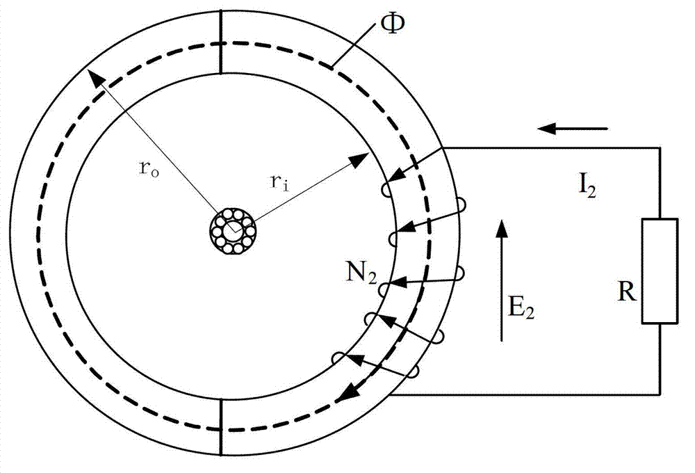
[0033] In order to analyze the power output characteristics of the power-taking coil, the load equivalent model of the power-taking coil established according to the basic electromagnetic induction theory is as follows: figure 1 shown.

[0034] According ...


PUM


Abstract

The invention provides a maximum power tracking system and a maximum power tracking method of a power transmission line induction power supply source. The method comprises the following steps of: detecting output voltage of a power supply coil and rectifying and amplifying the output voltage to obtain first output voltage; detecting output voltage of a measuring coil and performing rectification, amplification and phase-shift processing on the output voltage to obtain a reference voltage; outputting a drive control signal according to a comparison result of the two voltages; and switching on or off a switch tube by using the drive control signal to correspondingly select a battery or the power supply coil for supplying power for a load. By using the system and the method, the output voltage of the power supply coil can be adjusted by changing the duty ratio size of a gate drive signal of the switch tube to track the reference voltage all the time, thereby dynamically adjusting the output power of the power supply coil. In addition, when the power supply source and a backup battery are used for simultaneously supplying power, the time for supplying power for the load by the battery can be shortened to the greatest extent since the power supply coil works at the maximum power point for the most of time, so that the design life of the entire power supply source is prolonged.

Description

technical field [0001] The invention relates to an induction power acquisition technology of a high-voltage transmission line, in particular to a maximum power tracking system and method for an induction power acquisition power supply of a transmission line. Background technique [0002] The power supply problem of monitoring equipment on the high-voltage side of the power system is the prerequisite for the reliable operation of all monitoring equipment, and it is also one of the key technologies to be broken through in the construction of smart grids. For example, photoelectric current transformers, transmission line temperature measuring equipment, high-voltage circuit breaker busbar temperature measuring equipment, etc. directly measure the high-voltage side information, and then transmit the collected information to the low-voltage side through optical fiber or wireless network, which greatly simplifies the insulation requirements, and Improve the accuracy of the acquisi...

Claims


Application Information

Patent Timeline
IPC IPC(8): H02J17/00H02J9/06G05F1/67H02J50/10
Inventor 孙旭日李启昌刘亚东张洪伟孟昭利孙岳盛戈皞江秀臣
Owner 国网山东省电力公司聊城供电公司
Why Eureka
Try Eureka