Amplifier with automatic zero setting function and relevant detection module

An automatic zeroing and amplifier technology, applied in differential amplifiers, DC-coupled DC amplifiers, improved amplifiers to reduce noise effects, etc., can solve problems such as long charging time, input signal bandwidth limitation, and inability to process input signals. The effect of increasing the reaction rate and eliminating the offset voltage

Inactive Publication Date: 2013-03-06
RICHTEK TECH
View PDF4 Cites 0 Cited by
  • Summary
  • Abstract
  • Description
  • Claims
  • Application Information

AI Technical Summary

Problems solved by technology

[0004] However, it takes time to charge the capacitors in the auto-zero amplifier. If the number of capacitors is large or the capacitance value is large, the charging time will be longer, and the response rate of the auto-zero amplifier will be limited, making it impossible to handle An input signal with a rate of change that is too fast, resulting in a limitation of the bandwidth of the input signal

Method used


Image

  • Amplifier with automatic zero setting function and relevant detection module
  • Amplifier with automatic zero setting function and relevant detection module

Examples


Embodiment Construction

[0012] Embodiments of the present invention will be described below in conjunction with related figures. In the drawings, the same reference numerals indicate the same or similar components or process steps.

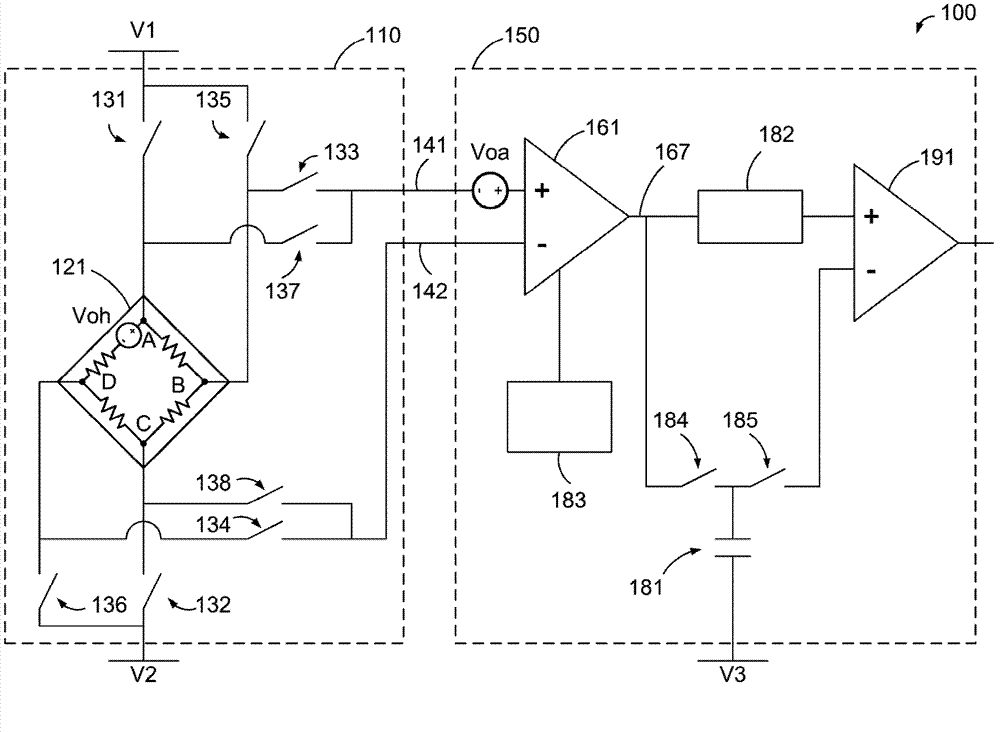
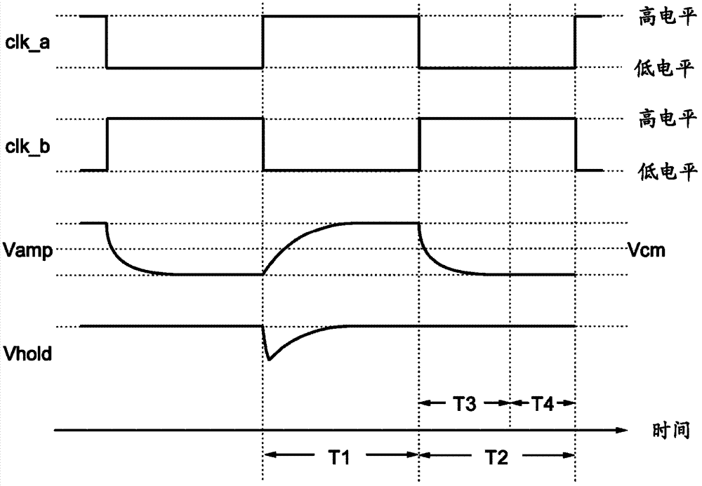
[0013] figure 1 It is a simplified functional block diagram of the detection module 100 according to an embodiment of the present invention. The detection module 100 includes a Hall effect detector 110 and an auto-zero amplifier 150 . figure 2 for application to figure 1 A simplified timing diagram of an embodiment of the control signal of the detection module 100, the following will be figure 1 match figure 2 The operation of the detection module 100 will be described.

[0014] The Hall effect detector 110 includes a Hall plate 121 , switches 131 - 138 , and output terminals 141 and 142 . The Hall plate 121 includes four terminals A, B, C and D. exist figure 1 In , the equivalent offset voltage of the Hall plate 121 is simulated by Voh between the terminals A a...


PUM


Abstract

An embodiment of the invention provides an amplifier with an automatic zero setting function. The amplifier comprises an amplifier circuit, switches and a difference value generating circuit. The amplifier circuit can receive a first input signal to generate a first output signal and can receive a second input signal to generate a second output signal. The switches are coupled between the amplifier circuit and a capacitor, when the switches are in short circuit states, the first output signal enables the capacitor to be charged or discharge to reach a voltage value, and when the switches are in open circuit states, the voltage value of the capacitor is kept. The difference value generating circuit is coupled with the amplifier circuit and the capacitor so as to generate a difference value between the first output signal and the second output signal, multiples of the difference value and / or parts of the difference value. The amplifier has the advantages that offset voltage of the amplifier with the automatic zero setting function and error voltage generated among different capacitors can be reduced, accurate amplified signals can be outputted, capacitor charging or discharging time can be shortened, and the response speed of the amplifier with the automatic zero setting function is increased.

Description

technical field [0001] The invention relates to an amplifier, in particular to an automatic zero-setting amplifier and a related comparison circuit which can be used to amplify tiny signals. Background technique [0002] In many system applications, it is necessary to use a detector to detect tiny signals, and then amplify the detected signals to facilitate subsequent signal processing. For example, a Hall effect sensor for detecting magnetic field strength can only generate a detection signal at the microvolt level when it detects a 1 Gauss magnetic field. If a general amplifier is used to amplify these tiny signals, the offset voltage of the detector (for example, Hall Plate) itself, the offset voltage generated by the components of the amplifier, or the noise of the circuit ) is often much larger than these small detection signals, which will make the detection signal amplified by the amplifier inaccurate. [0003] One of the amplifier architectures commonly used to han...

Claims


Application Information

Patent Timeline
Patent Type & Authority Applications(China)
IPC IPC(8): H03F3/45H03F1/26G01R31/07G01R31/74
Inventor 江学士陈安东汪若瑜纪壬弘
Owner RICHTEK TECH
Why Eureka
Try Eureka