Groove type cam folding and unfolding device for multiple seedling-taking end effectors
A technology of end effector and groove type, which is applied in the fields of planting methods, applications, agriculture, etc., can solve the problems of poor adaptability of plug trays, limited plug size, huge power drive system, etc., and achieves simple structure, low cost, and easy control Effect
- Summary
- Abstract
- Description
- Claims
- Application Information
AI Technical Summary
Problems solved by technology
Method used
Image

Examples
Embodiment Construction
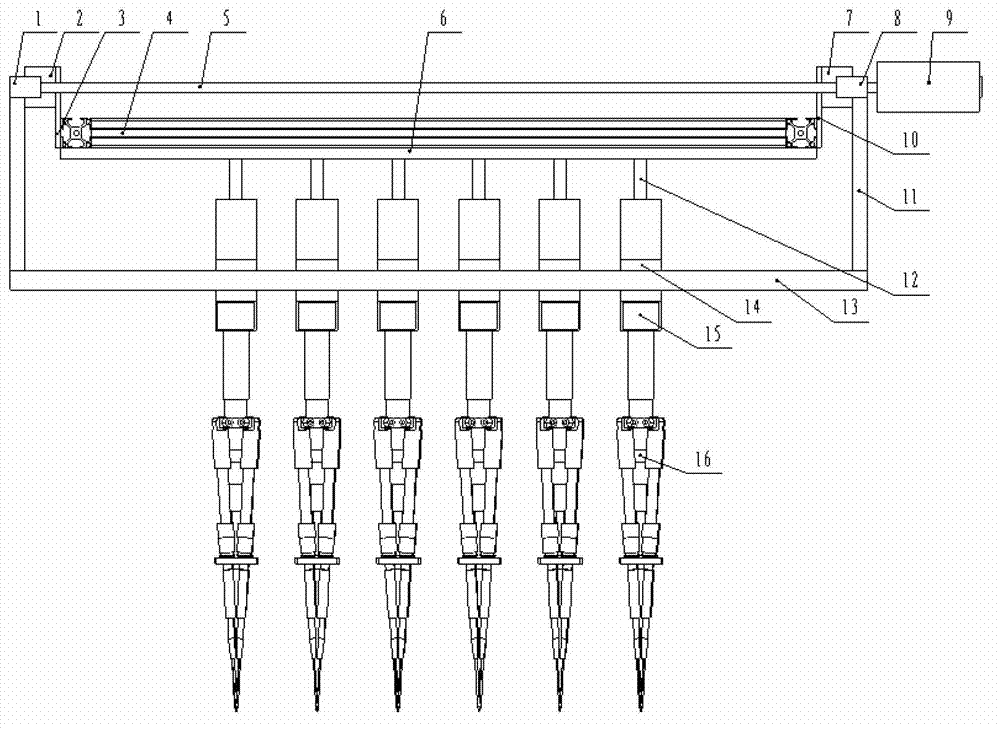
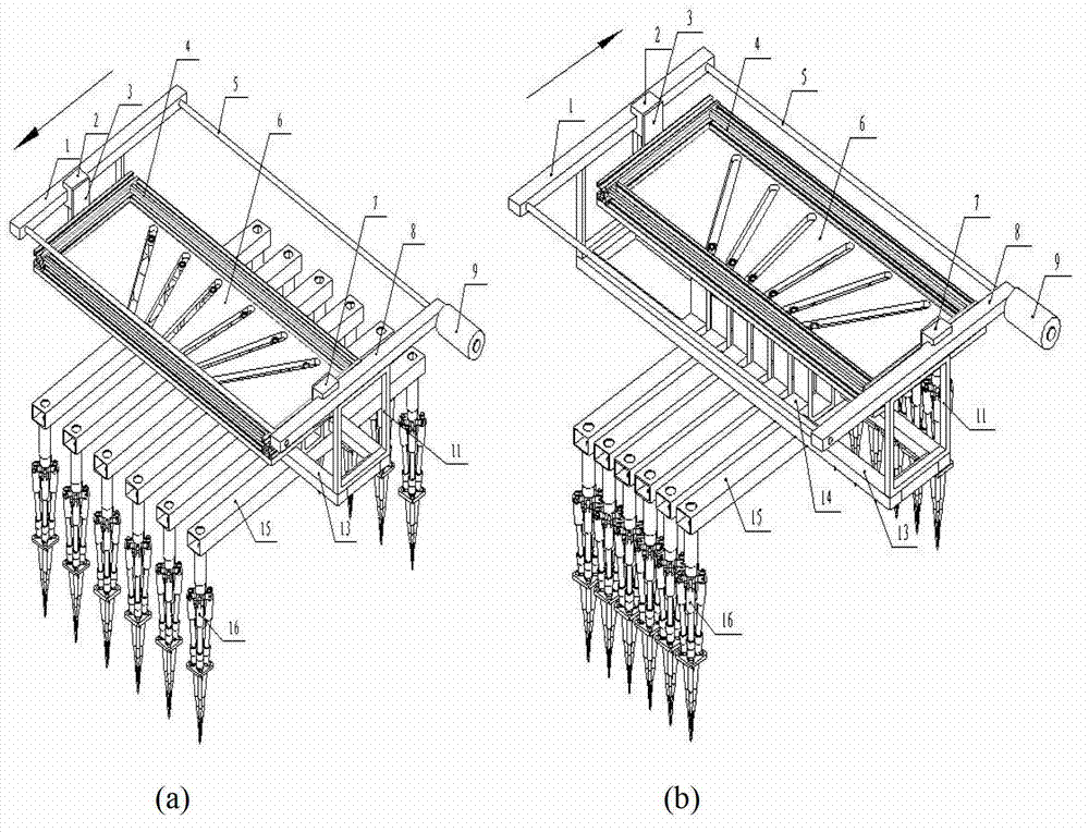
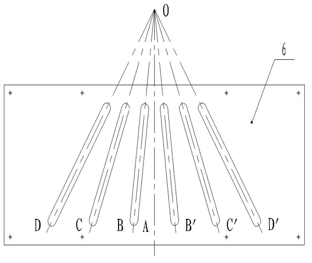
[0015] like figure 1 As shown, the overall structure of the present invention consists of a plywood, a synchronous belt guide rail, a linear guide rail, a square slider, a rotating shaft, a servo motor, a beam, and a mounting frame. The specific layout of each movement pair and parts is as follows: the plywood 6 is installed with the profile 4 along the edge, and is fixed on the square sliders 2 and 7 of the synchronous belt guide rails 1 and 8 through the mounting brackets 3 and 10, and the servo motor 9 The main shaft is equipped with a rotating shaft 5, which drives the synchronous belt guide rails 1 and 8, thereby pulling the square sliders 2 and 7 to drive the movement of the plywood 6. There are chutes with different inclination angles on the plywood 6, and each chute is assembled and installed. The ejector rod of the frame 12, the two sides of the mounting frame 12 are equipped with square sliders 14, which are installed on the linear guide rail 13 through the square sl...
PUM
 Abstract
Description
Claims
Application Information
 - Generate Ideas
- Intellectual Property
- Life Sciences
- Materials
- Tech Scout
- Unparalleled Data Quality
- Higher Quality Content
- 60% Fewer Hallucinations
Browse by: Latest US Patents, China's latest patents, Technical Efficacy Thesaurus, Application Domain, Technology Topic, Popular Technical Reports.
© 2025 PatSnap. All rights reserved.Legal|Privacy policy|Modern Slavery Act Transparency Statement|Sitemap|About US| Contact US: help@patsnap.com