Pipe fitting radial indexing drilling clamp tooling

A drilling jig and tooling technology, which is applied in the field of jigs and tooling, can solve problems such as not being able to meet the requirements of mass production, and achieve the effect of saving assembly time and ensuring assembly quality

Active Publication Date: 2013-03-13
HARBIN JIANCHENG GRP
View PDF6 Cites 35 Cited by
  • Summary
  • Abstract
  • Description
  • Claims
  • Application Information

AI Technical Summary

Problems solved by technology

[0003] The purpose of this invention is to solve the problem that the connecting holes on the outer circle of the existing pipe fittings are processed by boring and milling e

Method used


Image

  • Pipe fitting radial indexing drilling clamp tooling
  • Pipe fitting radial indexing drilling clamp tooling
  • Pipe fitting radial indexing drilling clamp tooling

Examples


specific Embodiment approach 1

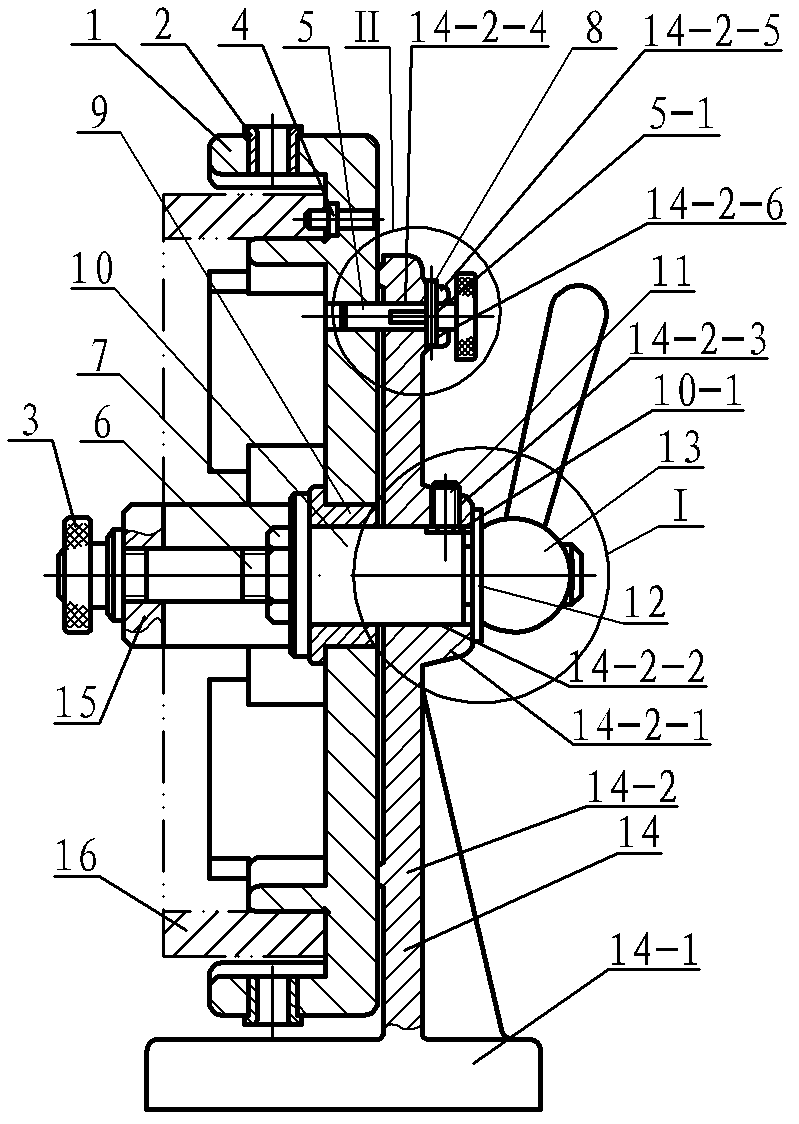
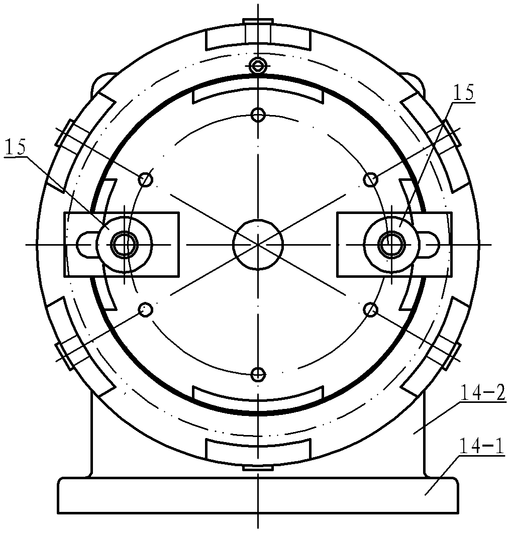
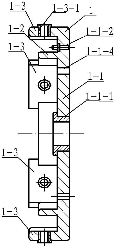
[0007] Specific implementation mode one: combine Figure 1 to Figure 6 Describe this embodiment, this embodiment includes index plate 1, positioning pin 4, index pin 5, two compression nuts 3, two compression screws 6, nut 7, limit pin 8, copper sleeve 9, center Shaft 10, positioning screw 11, fastening handle 13, clamp body 14, two pressure plates 15 and six drill sleeves 2, indexing plate 1 consists of plate base 1-1, four arc positioning plates 1-2 and six The arc formwork cover plates 1-3 are composed of six arc form form cover plates 1-3 which are evenly distributed along the edge of the side end face of the disc seat 1-1, and four arc form positioning plates 1-2 are evenly arranged on six In the inner chamber formed by two arc-shaped mold cover plates 1-3, and the outer circle diameter formed by the outer walls of the four arc-shaped positioning plates 1-2 is equal to the diameter of the inner hole of the processed pipe fitting 16, the four arc-shaped positioning plates ...

specific Embodiment approach 2

[0008] Specific implementation mode two: combination figure 1 and Figure 5 This embodiment is described. The difference between this embodiment and the first embodiment is that a large washer 12 is added, and the large washer 12 is arranged between the fastening handle 13 and the end surface of the first flange 14-2-1. Other components and connections are the same as those in the first embodiment.

[0009] The working principle of the present invention is: install the radial indexing drilling jig tooling of this pipe fitting on a radial drilling machine, and fix the base 14-1 of the jig body 14 on the working table of the drilling machine. When installing the jig, first Measure whether the clamp body 14 is perpendicular to the working surface of the equipment, and the center of each hole 2 of the drill bushing should be perpendicular to the working surface of the equipment. When the pipe fitting 16 to be processed is placed, the locating hole on the bottom surface of the pi...


PUM


Abstract

The invention relates to a pipe fitting radial indexing drilling clamp tooling, which relates to a clamp tooling of a pipe fitting excircle drilling work procedure and solves the problems that each connecting hole on the existing pipe fitting excircle is processed by boring and milling equipment and precise numerical control equipment, and the mass production requirements cannot be met. A drill bush is arranged in each drill bush hole arranged in an indexing disc, each screw rod hole arranged in the indexing disc is matched with one pressing screw rod, in addition, one end of the pressing screw rod is connected with the screw rod hole through screw threads, the other end of the pressing screw rod passes through a press plate to be connected with a pressing screw nut through screw threads, a positioning pin is arranged in a first positioning pin hole, a copper bush is arranged in a copper bush installing hole, a middle shaft is arranged in a middle shaft installing hole and an inner hole of the copper bush, a middle shaft at one end of the copper bush is connected with a screw nut through screw threads, a middle shaft of one end of a first flange is connected with a fastening handle through screw threads, a positioning screw and a positioning threaded hole are connected through screw threads, an indexing pin is embedded in a second positioning pin, and a position limiting pin is arranged in a first position limiting pin hole and a second position limiting pin hole. The clamp tooling is used for processing each hole on the excircle surface of pipe fittings.

Description

technical field [0001] The invention relates to a fixture tooling for the outer circle drilling process of pipe fittings. Background technique [0002] The connecting holes on the outer circle of the pipe fittings (with a wall thickness of 20 mm) require high precision distribution. The existing methods for processing the connecting holes on the outer circle of the pipe fittings are mostly processed by boring and milling equipment and precision numerical control equipment. Although boring and milling equipment can basically meet the positional accuracy requirements of each hole, additional steps such as clamping, alignment, and measurement in the process increase accordingly, which is time-consuming and laborious, and is not conducive to the normal progress of the entire production assembly. The use of precision numerical control equipment can better meet the position accuracy requirements of each hole, but its manufacturing cost is relatively high, which does not conform to...

Claims


Application Information

Patent Timeline
IPC IPC(8): B23B47/28B23Q3/06B23Q16/02
Inventor 丁学彬
Owner HARBIN JIANCHENG GRP
Why Eureka
Try Eureka