High-rigidity universal milling head with automatic rotating B shaft

A universal milling head, automatic rotation technology, applied in the driving device, metal processing mechanical parts, metal processing equipment and other directions, can solve the problems of the second type of universal milling head is expensive, prone to safety hazards, and the B axis needs to be manually adjusted. , to achieve the effect of large torque, eliminating safety hazards and improving labor productivity

Active Publication Date: 2014-12-17
沈阳机床中捷友谊厂有限公司
View PDF6 Cites 0 Cited by
  • Summary
  • Abstract
  • Description
  • Claims
  • Application Information

AI Technical Summary

Problems solved by technology

[0004] The purpose of the present invention is to provide a high-rigidity universal milling head with automatic rotation of the B-axis, which can simultaneously solve the problem of manual adjustment of the B-axis of the existing first universal milling head, low production efficiency, high cost, and prone to safety hazards. The second type of universal milling head is expensive, complex in structure, difficult to maintain and other technical problems

Method used


Image

  • High-rigidity universal milling head with automatic rotating B shaft
  • High-rigidity universal milling head with automatic rotating B shaft
  • High-rigidity universal milling head with automatic rotating B shaft

Examples


Embodiment Construction

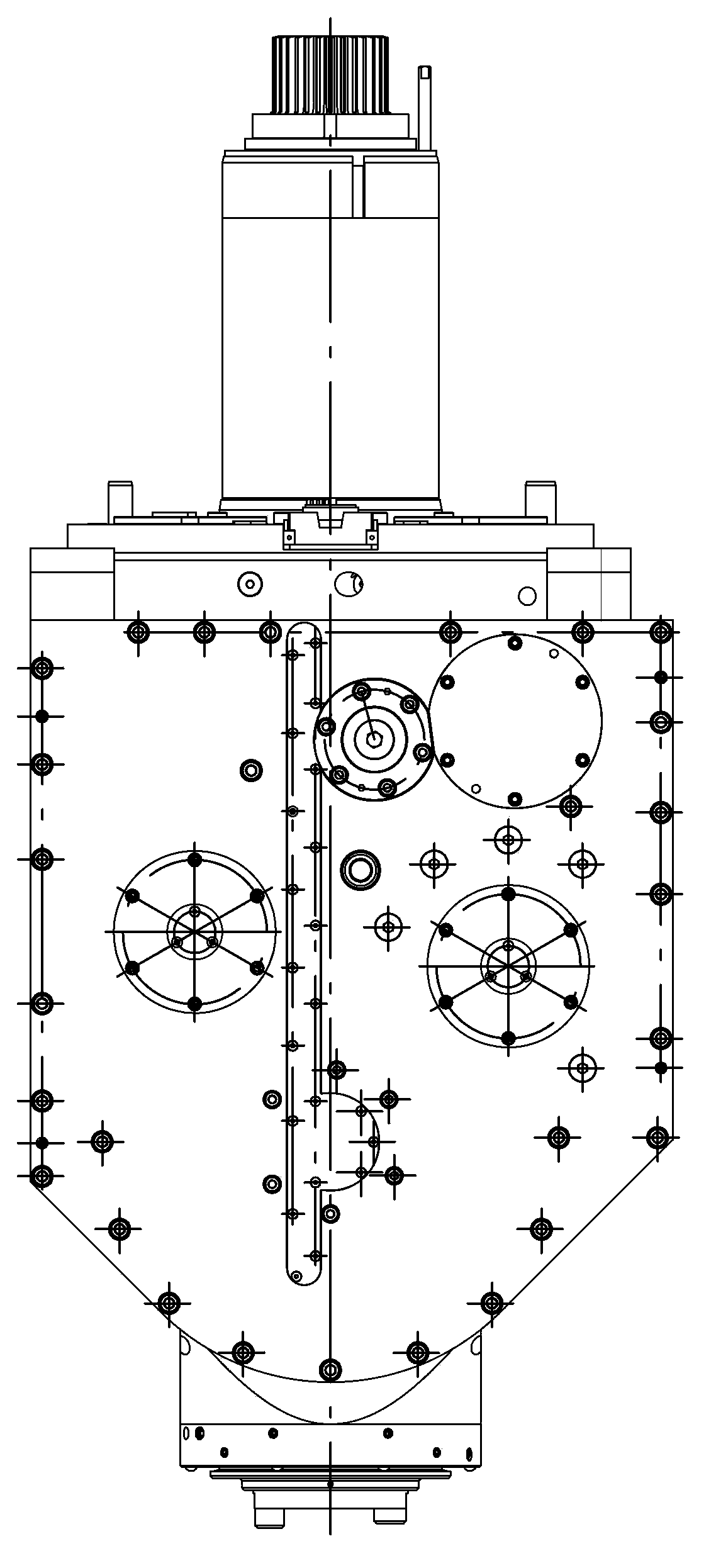
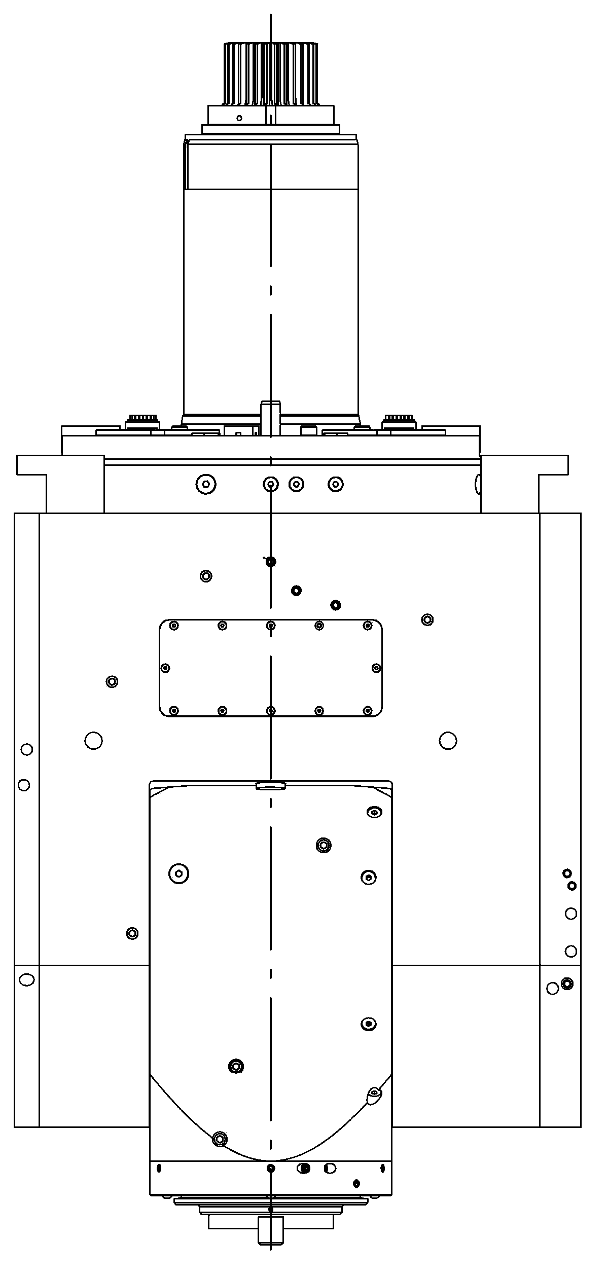
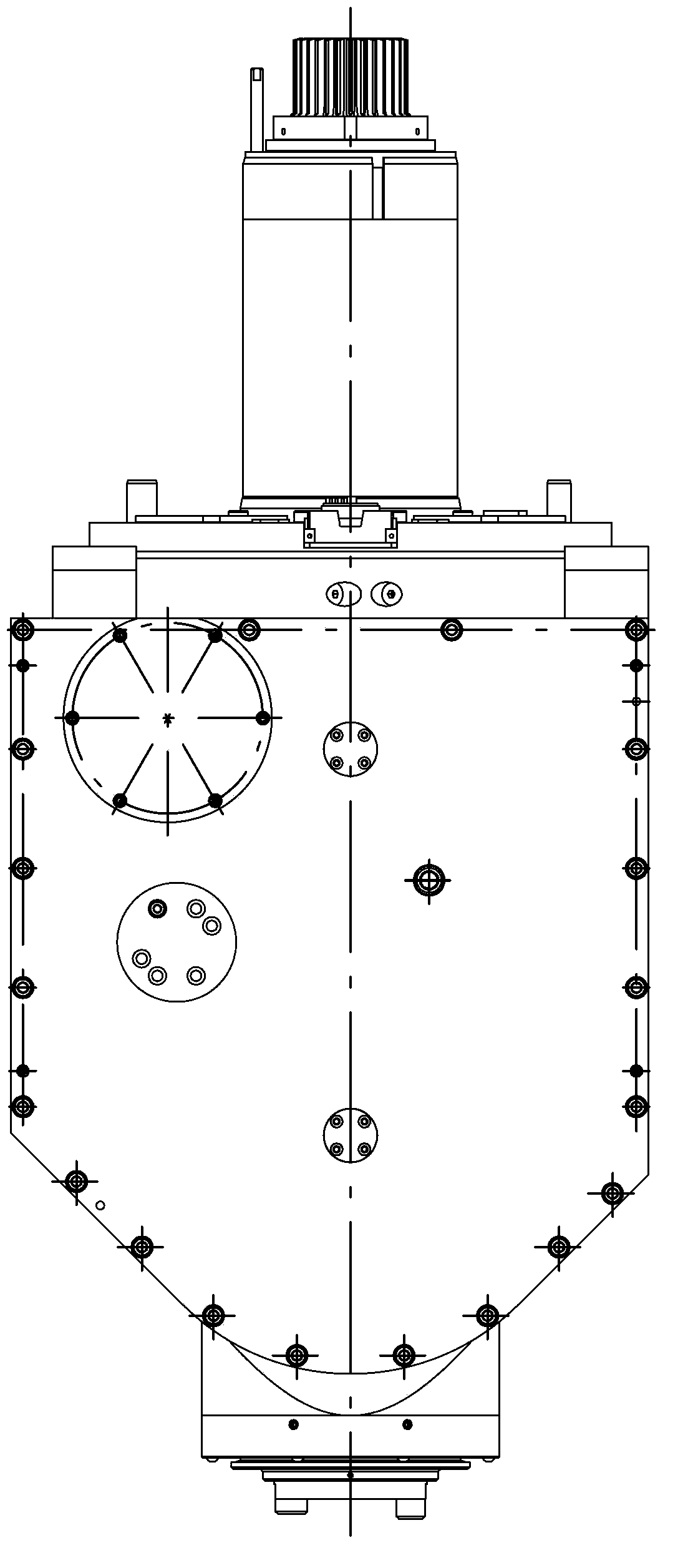
[0024] Highly rigid universal milling head with automatic rotation of the B axis, see Figure 1a-1c , The shell of the universal milling head is hollow, and the tool spindle is installed in the middle of the lower part. It is characterized in that the milling power gear mechanism and the B-axis power gear mechanism are installed on both sides of the universal milling head shell.

[0025] see Figure 2a-Figure 2d , hide the internal structure diagram of the universal milling head shell for the universal milling head. as the picture shows, Figure 2a The B-axis power gear mechanism is installed on the left side, and the milling power gear mechanism is installed on the right side. The Siemens built-in motor 1 is installed in the universal milling head shell, and is the power source of the B-axis power gear mechanism. Its output end is connected to the planetary gear reducer 2, the reduction ratio is i=22, and the output end of the reducer is a flange output. , connecting the i...


PUM


Abstract

The invention relates to a high-rigidity universal milling head with an automatic rotating B shaft. The high-rigidity universal milling head with the automatic rotating B shaft comprises two gear mechanisms, is connected with a ram through an automatic tensioning device and is characterized in that a milling and cutting power gear mechanism and a B shaft power gear mechanism are respectively arranged on the two sides of a universal milling head shell, and a cutter main shaft shell is installed between the milling and cutting power gear mechanism and the B shaft power gear mechanism; a first bevel gear pair is installed at the lower end of the spline shaft of the milling and cutting power gear mechanism and is radially connected with a second bevel gear pair through a gear on a transition shaft, the second bevel gear pair is connected onto a cutter main shaft; and the output end of the motor of the B shaft power gear mechanism is connected with a planetary reducer with reduction ratio i being equal to 22, the output end of the motor of the B shaft power gear mechanism is connected with B shaft primary and secondary gears and dual anti-backlash gears and is connected to one end of a B shaft tertiary gear, and the other end of the B shaft tertiary gear is connected with the cutter main shaft shell through a flange in a fastening way. The high-rigidity universal milling head with the automatic rotating B shaft has the advantages that the goal of machining through B shaft feeding can be realized, the positioning accuracy is high, the potential safety hazard is eliminated and the productivity is improved; and since a B shaft mechanism and a milling and cutting mechanism are gear mechanisms for power transmission, the layout is reasonable, the cost is saved and the mass production can be realized.

Description

technical field [0001] The invention relates to a mechanical equipment component, in particular to a high-speed, high-rigidity automatic tool changing belt B-axis processing device, which is mainly used for large vertical turning and milling centers and boring and milling centers. Background technique [0002] At present, there are two structures of universal milling heads used in vertical turning and milling centers and gantry boring and milling centers: one is the structure of the milling head with B-axis manual rotation and spindle rotation using electric spindle. In this structure, when machining workpieces with angles (such as machining angled holes and grooves), it is necessary to adjust the hand wheel on the attachment head, manually adjust the B-axis to the required angle, and then proceed to process. This kind of universal milling head has a simple structure, the B-axis cannot participate in the cutting feed of the machine tool, and the price is cheap, but it increa...

Claims


Application Information

Patent Timeline
Patent Type & Authority Patents(China)
IPC IPC(8): B23Q5/10B23Q5/22
Inventor 贺鑫元尹晓霞喻鹏蒋琳赵旭靖齐延男周兴福
Owner 沈阳机床中捷友谊厂有限公司
Why Eureka
Try Eureka