Updraft multistage automatic cup distributing system

A multi-station, automatic technology, applied in the direction of conveyors, conveyor objects, transportation and packaging, etc., can solve the problems of high negative pressure, large floor space, and complex structure of the cup output components, and achieve reliable and timely output of cups. The effect of simplifying the structure and reducing energy consumption

Active Publication Date: 2014-12-24
岸宝环保科技(南京)有限公司
View PDF7 Cites 0 Cited by
  • Summary
  • Abstract
  • Description
  • Claims
  • Application Information

AI Technical Summary

Problems solved by technology

[0003] The purpose of the present invention is to solve the problem that the existing cup distributing system requires multiple conveyor belts and high negative pressure inside the cup outlet assembly, resulting in complex structure of the whole system, high energy consumption, high cost, and large floor space , providing an up-suction multi-station automatic cup dispensing system

Method used


Image

  • Updraft multistage automatic cup distributing system
  • Updraft multistage automatic cup distributing system
  • Updraft multistage automatic cup distributing system

Examples


Embodiment

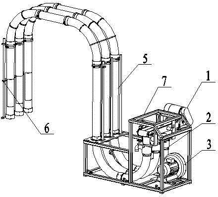
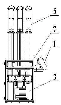
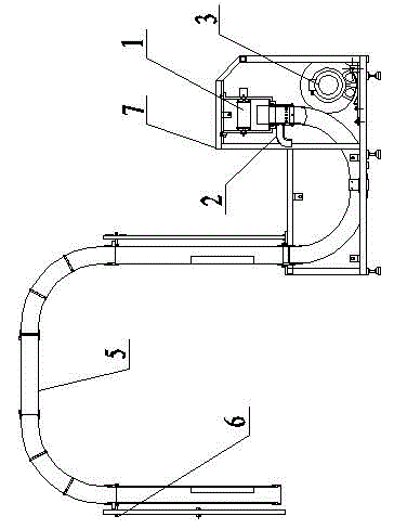
[0048] Such as figure 1 , figure 2 , image 3 with Figure 4 As shown, the upper suction multi-station automatic cup dividing system includes an upper suction conveyor 1, a cup outlet assembly 2 and a fan 3. The upper suction conveyor 1 is set directly above the cup outlet assembly 2. 2 includes at least one cup outlet tube 201, the suction port of the fan 3 is connected with the upward suction conveyor 1, and the outlet of the fan 3 is connected with the cup outlet assembly 2. The upper suction conveyor 1, the cup out assembly 2 and the fan 3 are fixed on the frame 7

[0049] The upward suction conveyor 1 is arranged directly above the cup outlet assembly 2, and the paper-plastic cup 8 can directly fall into the cup outlet assembly 2 under the action of gravity, and there is no need to generate negative pressure inside the cup outlet assembly 2. The cup-out assembly 2 includes at least one cup-out barrel 201, which enables one cup-out assembly 2 to correspond to at least one su...


PUM


Abstract

The invention discloses an updraft multistage automatic cup distributing system which comprises an updraft conveyer, a cup discharging component and a fan, wherein the updraft conveyer is arranged rightly above the cup discharging component which comprises at least one cup discharging cylinder, an air inlet of the fan is connected with the updraft conveyer, and an air outlet of the fan is connected with the cup discharging component. The updraft multistage automatic cup distributing system disclosed by the invention has the advantages as follows: the upright conveyer is arranged rightly above the cup discharging component, plastic cups can directly fall into the cup discharging component by negative pressure generated by the cup discharging cylinder and self gravity of the plastic cups, so the cup discharge is more reliable and timely simultaneously with decreasing the wind energy and saving the energy consumption; and the cup discharging component comprises at least one cup discharging cylinder, so that one upright conveyer can be corresponding to at least one subsequent device by one cup discharging component to simplify the structure of the whole system.

Description

Technical field [0001] The invention relates to a device for orderly collecting materials, in particular to a suction-type multi-station automatic cupping system. Background technique [0002] On the paper-plastic cup production line, the paper-plastic cups produced need to be clearly machined and sorted, so that they can enter the outer sticking machine in an orderly manner to complete the subsequent processes. The traditional cup dividing system adopts an upward dividing method to divide the cups. The cup-out assembly is arranged above the conveyor. The paper-plastic cup moves from one end of the conveyor to the other, and then enters the cup dividing device at the end of the conveyor. A cup-out component has only one inlet, and each cup-out component needs to correspond to a conveyor belt separately, that is, as many conveyor belts as there are in the subsequent process, the structure of the whole system is complicated, the cost is high, and the cost is high. The land area is...

Claims


Application Information

Patent Timeline
Patent Type & Authority Patents(China)
IPC IPC(8): B65G15/58B65G47/34B65G47/52
Inventor 余家荣田洪勇
Owner 岸宝环保科技(南京)有限公司
Why Eureka
Try Eureka