Coupling polarizer assembly and ips mode liquid crystal display device with the coupling polarizer assembly
A polarizing plate and component technology, applied in optical elements, polarizing elements, optics, etc., can solve problems such as change, delay, and brightness, and achieve the effects of flexible use, excellent color sense, and excellent viewing angle
- Summary
- Abstract
- Description
- Claims
- Application Information
AI Technical Summary
Problems solved by technology
Method used
Image
Examples
Embodiment 1
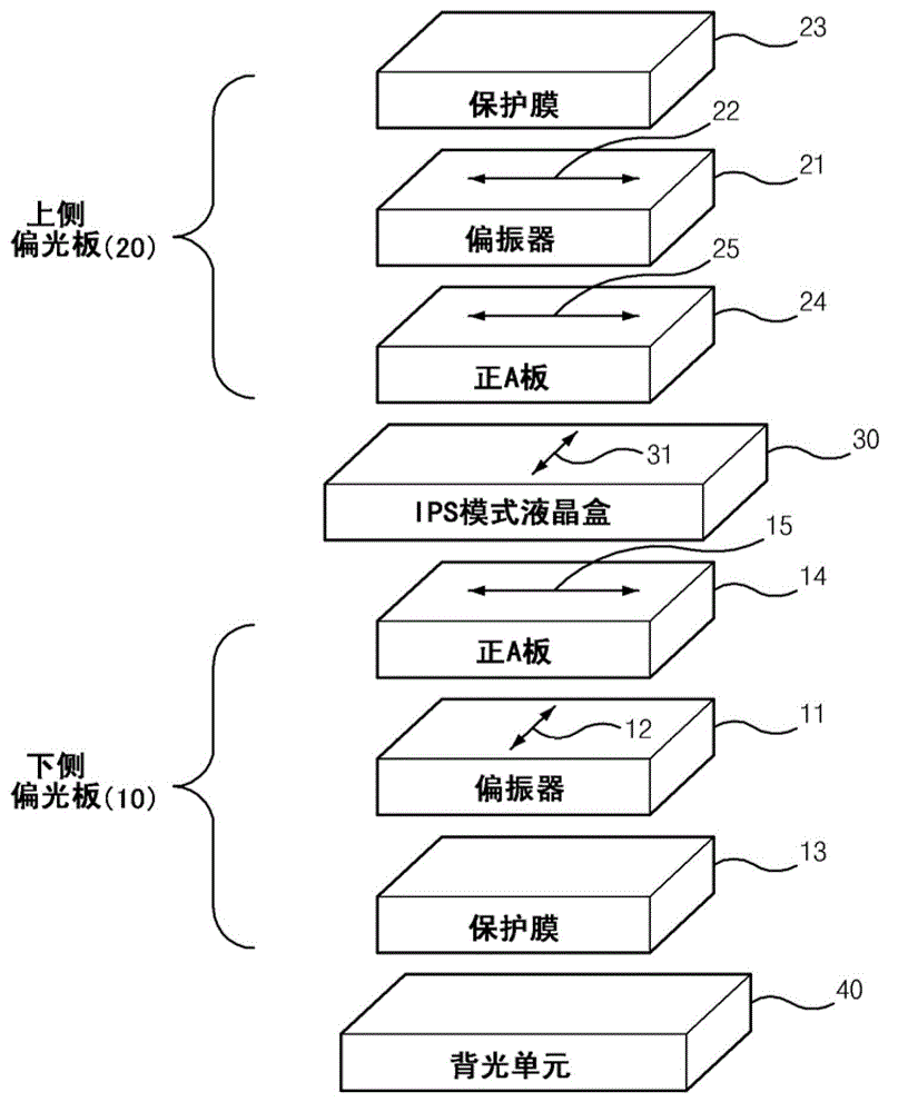
[0108] in such as figure 1 The lamination was performed as shown, and the actual measurement data of each optical film, liquid crystal cell, and backlight involved in the present invention were used in TECHWIZLCD1D (SANAYISYSTEM Co., Ltd., Korea). The following pairs figure 1 The structure is described in detail.
[0109] From the side of the backlight unit 40, it consists of a lower polarizer 10, an IPS mode liquid crystal cell 30, and an upper polarizer 20, wherein the IPS mode liquid crystal cell 30 is the right side of the visible side in a state where no voltage is applied. The IPS mode liquid crystal cell 30 in which the liquid crystal alignment direction is 90° when the counterclockwise rotation is taken as the positive (+) direction based on the lateral horizontal direction. In the lower polarizing plate 10, a positive A plate 14, a polarizer 11, and a protective film 13 are laminated from the liquid crystal cell side. In the upper polarizing plate 20, a positive A ...
Embodiment 2
[0130]Although configured in the same manner as in Example 1 above, the positive A plate 24 of the upper polarizing plate 20 uses an in-plane retardation value (R0) of 50 nm, a thickness direction retardation value (Rth) of 25 nm, and a refractive index ratio (NZ) is a positive A plate of 1.0.
[0131] In addition, the positive A plate 14 of the lower polarizing plate 10 uses a positive A plate with an in-plane retardation value (R0) of 80 nm, a thickness direction retardation value (Rth) of 40 nm, and a refractive index ratio (NZ) of 1.0, thereby producing IPS mode liquid crystal display device.
Embodiment 3
[0133] Although configured in the same manner as in Example 1 above, the positive A plate 24 of the upper polarizing plate 20 uses an in-plane retardation value (R0) of 80 nm, a thickness direction retardation value (Rth) of 40 nm, and a refractive index ratio (NZ) is a positive A plate of 1.0.
[0134] In addition, the positive A plate 14 of the lower polarizing plate 10 uses a positive A plate with an in-plane retardation value (R0) of 80 nm, a thickness direction retardation value (Rth) of 40 nm, and a refractive index ratio (NZ) of 1.0, thereby producing IPS mode liquid crystal display device.
PUM
| Property | Measurement | Unit |
|---|---|---|
| degree of polymerization | aaaaa | aaaaa |
Abstract
Description
Claims
Application Information
 - R&D
- Intellectual Property
- Life Sciences
- Materials
- Tech Scout
- Unparalleled Data Quality
- Higher Quality Content
- 60% Fewer Hallucinations
Browse by: Latest US Patents, China's latest patents, Technical Efficacy Thesaurus, Application Domain, Technology Topic, Popular Technical Reports.
© 2025 PatSnap. All rights reserved.Legal|Privacy policy|Modern Slavery Act Transparency Statement|Sitemap|About US| Contact US: help@patsnap.com


