Intervertebral space fusion device and pusher for advancing it

A fusion device and intervertebral space technology, applied in medical science, prostheses, joint implants, etc., can solve the problems of limited bone graft quantity, increase implant notch, increase operation time and risk, etc., and achieve improved stability performance, increased speed and quality, and reduced size and kerf

Active Publication Date: 2015-12-09
SHANGHAI SANYOU MEDICAL CO LTD
View PDF8 Cites 0 Cited by
  • Summary
  • Abstract
  • Description
  • Claims
  • Application Information

AI Technical Summary

Problems solved by technology

[0005] Because the existing intervertebral space fusion device adopts a closed structure to accommodate and carry the graft bone, the amount of implanted bone graft is very limited, and a certain amount of shedding will inevitably occur during implantation, which cannot ensure the compactness of the graft bone. Moreover, after implantation, there is a certain gap between the grafted bone and the surface of the vertebral body endplates at both ends of the intervertebral space, which affects the speed and quality of fusion; in addition, after implanting the intervertebral fusion cage in the intervertebral space, it is necessary to implant auxiliary fixation devices to ensure The intervertebral space fusion device will not deviate from the original position, ensuring the stability of the fusion segment; the commonly used auxiliary fixation device is a fixed plate, which is fixedly connected to the upper and lower vertebral bodies through screws; the implantation of the fixed plate not only increases the surgical time and risk, also increases the notch of the implant

Method used


Image

  • Intervertebral space fusion device and pusher for advancing it
  • Intervertebral space fusion device and pusher for advancing it
  • Intervertebral space fusion device and pusher for advancing it

Examples


Embodiment Construction

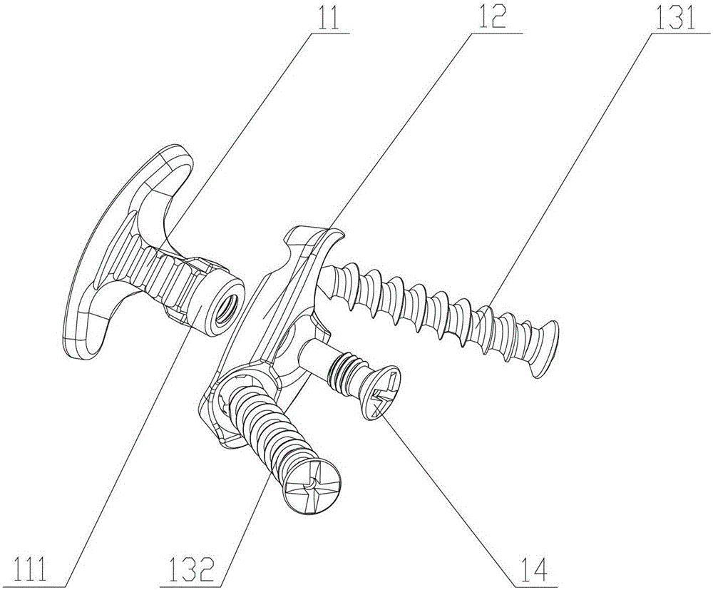
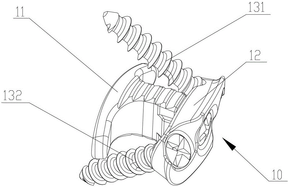
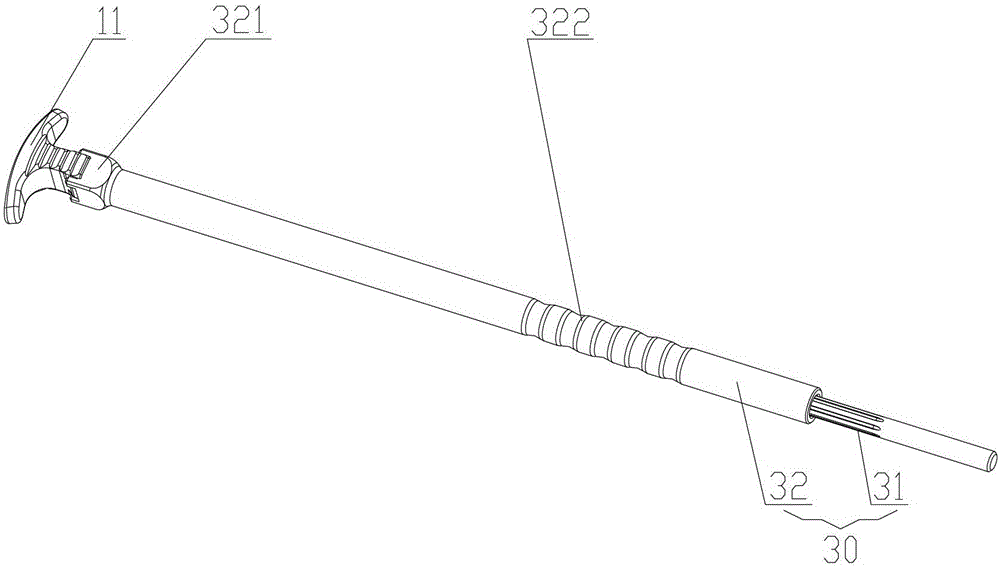
[0033] The core of the present invention is to provide an intervertebral fusion cage, which can provide sufficient bone graft space, ensure that the graft bone has close contact with the vertebral body endplate, and improve the speed and quality of intervertebral body fusion. Another core of the present invention is to provide a propulsion guide rod for propelling the intervertebral fusion cage.

[0034] In order to enable those skilled in the art to better understand the solution of the present invention, the present invention will be further described in detail below with reference to the accompanying drawings and specific embodiments.

[0035] What needs to be explained here is that the upper, lower and middle localizers involved in this article are Figure 1 to Figure 8 The middle parts are defined by the position of the parts in the figure and between the parts, just to express the technical solution clearly and conveniently. It should be understood that the use of the locatio...


PUM


Abstract

The invention discloses an intervertebral fusion device, which comprises a fusion device body used for keeping distance between adjacent centrums, wherein the fusion device body comprises a cross beam and a vertical beam fixedly connected with the cross beam, when the fusion device body is arranged between the adjacent centrums, a space for accommodating bone graft is formed by the cross beam and soft tissues on two sides of the cross beam. The intervertebral fusion device also comprises a fixed connecting block connected with the tail part of the fusion device body in a sleeved manner and used for connecting the adjacent centrums. According to the intervertebral fusion device provided by the invention, a closed structure of the intervertebral fusion device in the prior art is changed into an opened structure, the intervertebral fusion device is allowed to be implanted into an intervertebral space and the bone graft is filled in the intervertebral space, an enough distribution space of the bone graft in the intervertebral space is ensured, centrum terminal plates on two ends of the intervertebral space can be tightly contacted and the speed and the quality of intervertebral fusion are increased. The invention also provides a propeller for pushing the intervertebral fusion device into the intervertebral space.

Description

Technical field [0001] The invention relates to a spinal internal fixation device, in particular to an intervertebral fusion cage. In addition, the present invention also relates to a propeller for propelling the intervertebral fusion cage. Background technique [0002] Intervertebral fusion refers to the operation of implanting grafted bone tissue or artificial bone tissue after the soft tissue is removed from the diseased intervertebral disc to promote the formation of fusion between two vertebral bodies. The internal implant commonly used in surgery is an intervertebral fusion cage, which is placed on the diseased intervertebral disc. [0003] The main function of the intervertebral fusion cage is to accommodate and carry grafted bone tissue or artificial grafted bone and maintain the height between the vertebral bodies during the fusion process. As the core part of intervertebral space fusion, the intervertebral fusion cage should not only provide a good carrier for the bone ...

Claims


Application Information

Patent Timeline
Patent Type & Authority Patents(China)
IPC IPC(8): A61F2/44A61F2/46
CPCA61F2/44A61F2002/30001
Inventor 袁文刘明岩张文桥
Owner SHANGHAI SANYOU MEDICAL CO LTD
Why Eureka
Try Eureka