
Compound anti-channeling gas-liquid separator

A gas-liquid separator, a composite technology, applied in separation methods, dispersed particle separation, combined devices, etc., can solve the problem that the separator cannot automatically control the gas-liquid flow rate, etc., achieve compact structure, high-efficiency separation, and prevent gas-liquid reaction. channeling effect

Inactive Publication Date: 2013-03-20
邢学军
View PDF4 Cites 9 Cited by
  • Summary
  • Abstract
  • Description
  • Claims
  • Application Information

AI Technical Summary

Problems solved by technology

[0004] The purpose of the present invention is to solve the problem that the separator integrating multiple separation mechanisms cannot automatically control the gas-liquid flow rate, and to provide an automatic adjustment that does not require the compounding of external energy sources Anti-channeling gas-liquid separator, which first pre-separates the mixed liquid through a closed spiral conduit, then uses an open spiral conduit to degas the pre-separated liquid, and uses baffles and adsorption filters to purify the gas

Method used


Image

  • Compound anti-channeling gas-liquid separator
  • Compound anti-channeling gas-liquid separator
  • Compound anti-channeling gas-liquid separator

Examples


Embodiment Construction

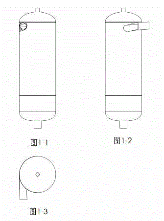
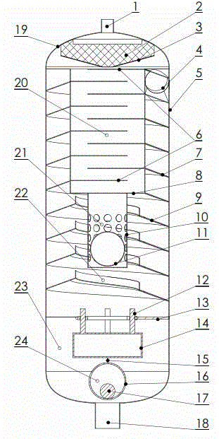
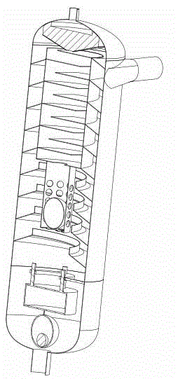
[0025]   As shown in the figure, the composite anti-channeling gas-liquid separator includes an exhaust pipe 1, an adsorption filter 2, an inverted conical partition 3, a feed port 4, a shell 5, a baffle 6, a closed spiral Conduit 7, gas-liquid chamber partition 8, open spiral conduit 9, valve ball conduit 10, hollow valve ball a11, guide rail 12, centralizer 13, columnar float 14, connecting rod 15, hollow valve ball b16, heavy ball 17 , liquid discharge pipe 18, top cover 19, air cavity 20, exhaust self-control valve 21, separation chamber 22, liquid collection chamber 23 and liquid discharge self-control valve 24;

[0026]    The top of the vertically placed cylindrical shell 5 is provided with a top cover 19, the upper part is provided with a feed inlet 4, and the inner side is provided with a closed spiral conduit 7 and an open spiral conduit 9, and the entrance of the closed spiral conduit 7 is connected to the feed inlet 4. Connected with each other, the lower end of ...


PUM


Abstract

The invention discloses a compound anti-channeling gas-liquid separator. The technical scheme of the invention is as follows: the top end of a vertically-arranged cylindrical shell is provided with a top cover, the upper part of the shell is provided with a feed inlet, the inner side of the shell is provided with a spiral duct, the inlet of the spiral duct is connected with the feed inlet, the lower end of the shell is provided with a liquid collecting cavity, and a central shaft is provided with a cylindrical gas cavity; the upper end of the top cover is provided with an exhaust pipe, the center of the inside surface of the top cover is provided with an adsorption filter, and the bottom of the adsorption filter is provided with an inverted conical partition plate; the top of the liquid collecting cavity is provided with a centralizer, the center of the liquid collecting cavity is provided with a drainage automatic control valve, and the lower end of the liquid collecting cavity is provided with a drainage pipe; and the inner wall surface of a gas cavity is provided with a horizontal baffle plate, the bottom of the gas cavity is provided with a gas-liquid cavity partition plate, the center of the gas-liquid cavity partition plate is provided with a gas guide hole, and the lower end of the gas-liquid cavity partition plate is provided with an exhaust automatic control valve. The compound anti-channeling gas-liquid separator disclosed by the invention is compact in structure; various separation mechanisms such as centrifugal separation, impact, condensed capturing, gravity separation, adsorption filtration and inertial separation are integrated in one separator; and the separator has a function of preventing gas and liquid from channeling, and can meet the efficient separation of gas and liquid.

Description

technical field [0001] The present invention relates to a gas-liquid separator, in particular to a composite anti-channeling gas-liquid separator, which is suitable for the separation of various gas-liquid mixtures whose gas-liquid proportion changes at any time. Background technique [0002] In actual production and application, because the gas content changes at any time, the gas-liquid ratio of the separator is out of balance, and the phenomenon of liquid in the exhaust line or gas in the discharge line appears, which affects production; at the same time, many gas-liquid separators have The volume is large, the separation effect is not obvious, and the defects of liquid droplets in the separated gas. [0003] The separation mechanism of the current separator mainly includes centrifugal separation, gravity separation, impact, condensation capture, adsorption filtration and inertial separation. The separator integrates multiple separation mechanisms of impact, condensation...

Claims


Application Information

Patent Timeline
Patent Type & Authority Applications(China)
IPC IPC(8): B01D50/00
Inventor 邢学军贾艳艳李善存刘瑞环胡光
Owner 邢学军
Learn More