Manufacturing method of low-melting-point glass optical fiber perform coating sleeve pipe

A low-melting-point glass and optical fiber preform technology, applied in glass manufacturing equipment, manufacturing tools, etc., can solve the problems of large interface loss and complex manufacturing process, reduce impurities and bubble loss, simple and fast operation, and avoid bubble streaks Effect

Inactive Publication Date: 2013-03-20
苏州佳因特光电科技有限公司
View PDF6 Cites 2 Cited by
  • Summary
  • Abstract
  • Description
  • Claims
  • Application Information

AI Technical Summary

Problems solved by technology

The invention solves the problems of large interface loss and complicated manufacturing process in the manufacturing process of the existing low-melting point glass optical fiber preform

Method used


Image

  • Manufacturing method of low-melting-point glass optical fiber perform coating sleeve pipe

Examples


Embodiment 1

[0026] A method for preparing a cladding sleeve of a tellurite glass optical fiber preform, comprising the following steps:

[0027] (1) melting tellurate glass, cooling and crushing for subsequent use;

[0028] (2) Design the inner and outer diameters of the tellurite glass casing, and select a quartz tube of the corresponding size;

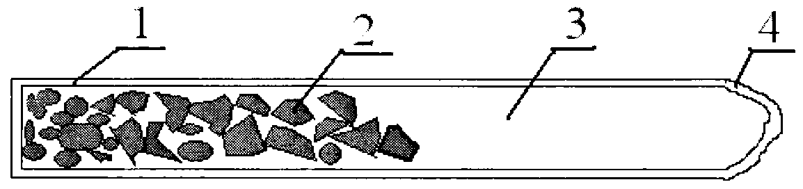
[0029] (3) Calculate and accurately weigh the tellurite glass and then pack it into a quartz tube;

[0030] (3) Heating the bottom of the charged quartz tube to 150-300°C, and then sealing it with flame;

[0031] (4) Put the sealed quartz tube into a swing furnace, slowly heat up to melt the glass in the tube to a liquid state;

[0032] (5) Turn on the swing switch of the electric furnace and swing for about 10 minutes to make the glass liquid mix evenly;

[0033] (6) Turn on the electric furnace, quickly take out the quartz tube and put it horizontally into the rotating device, fix the quartz tube and rotate it at a speed of 3000 rpm for 3 t...

Embodiment 2

[0037] A method for preparing the cladding sleeve of an oxyfluorine tellurate glass optical fiber preform, comprising the following steps:

[0038] (1) melting oxyfluorine tellurate glass, cooling and crushing for subsequent use;

[0039] (2) Design the inner and outer diameters of the tellurite glass casing, and select a quartz tube of the corresponding size;

[0040] (3) Calculate and accurately weigh the tellurite glass and then pack it into a quartz tube;

[0041] (3) Heat the bottom of the charged quartz tube to 150-200°C, vacuumize to make the pressure in the tube lower than one atmospheric pressure, and then seal it with flame;

[0042] (4) Put the sealed quartz tube into a swing furnace, slowly heat up to melt the glass in the tube to a liquid state;

[0043] (5) Turn on the swing switch of the electric furnace and swing for about 30 minutes to make the glass liquid mix evenly;

[0044] (6) Turn on the electric furnace, quickly take out the quartz tube and put it ho...

Embodiment 3

[0048] A method for preparing a cladding sleeve of a chalcogenide optical fiber preform, comprising the steps of:

[0049] (1) melting chalcogenide glass, cooling and crushing for subsequent use;

[0050] (2) Design the inner and outer diameters of the chalcogenide glass casing, and select a quartz tube of the corresponding size;

[0051] (3) Calculate and accurately weigh the tellurite glass and then pack it into a quartz tube;

[0052] (3) Heat the bottom of the charged quartz tube to 90-250°C, and vacuumize the tube to make the pressure in the tube lower than 10 -2 Pa, and then sealed with flame;

[0053] (4) Put the sealed quartz tube into a swing furnace, slowly heat up to melt the glass in the tube to a liquid state;

[0054] (5) Turn on the swing switch of the electric furnace to swing for more than 1 hour to make the glass liquid mix evenly;

[0055] (6) Turn on the electric furnace, quickly take out the quartz tube and put it horizontally into the rotating device,...


PUM

PropertyMeasurementUnit
melting pointaaaaaaaaaa
glass transition temperatureaaaaaaaaaa

Abstract

The invention relates to a manufacturing method of a low-melting-point glass optical fiber perform coating sleeve pipe. The method belongs to the technical field of glass optical fiber manufacturing. The method is characterized in that the preparation of the coating sleeve pipe comprises the steps that: (1) low-melting-point glass is molten, cooled, and crushed; and the glass is preserved for later use; (2) the low-melting-point glass is weighed and placed in a quartz tube; (3) the loaded quartz tube is vacuumed and sealed; (4) the sealed quartz tube is heated in a rocking furnace, such that the glass in the tube is molten into liquid; (5) an electric furnace rocking switch is tuned on, such that the glass liquid is well mixed; (6) the electric furnace is opened, the quartz tube is rapidly fetched and horizontally placed in a rotation device; the quartz tube is fixed, and high-speed rotation is carried out; (7) the quartz tube is fetched, and is rapidly annealed in an annealing furnace; and (8) the quartz tube is cracked, such that the coating sleeve pipe obtained. The method has the advantages that the manufactured coating sleeve pipe has smooth and non-polluted inner surface, controllable inner and outer diameters, and no bubble and line inside.

Description

technical field [0001] The invention relates to a method for manufacturing an optical fiber prefabricated rod cladding sleeve, and belongs to the technical field of glass optical fiber manufacturing. It is especially suitable for the production of low-melting point glass optical fiber preform cladding sleeves of various substrates. Background technique [0002] With the gradual maturity of infrared optical material preparation technology and the increasing development of infrared light sources, infrared optical products are growing explosively. Because heavy metal oxides, oxyhalides, halides, and chalcogenides have good transmission properties in low-melting glass fibers such as air-transparent mid-wave infrared (3-5 microns) and long-wave infrared (8-12 microns), so in Optical fiber communication, infrared detection, chemical sensing analysis, infrared imaging, infrared laser transmission, biomedicine and other fields have shown great application value. [0003] The tradi...

Claims


Application Information

Patent Timeline
Patent Type & Authority Applications(China)
IPC IPC(8): C03B37/012
CPCC03B37/01268
Inventor 汪国年
Owner 苏州佳因特光电科技有限公司
Why Eureka
Try Eureka