
Comprehensive monitoring system for electric power system transformers

A comprehensive monitoring system and power transformer technology, applied in the field of transformers, can solve problems such as increased procurement costs, inconvenience for operation and maintenance personnel, and increased management costs

Active Publication Date: 2013-03-20
SHENZHEN SHUANGHE ELECTRIC CO LTD
View PDF9 Cites 55 Cited by
  • Summary
  • Abstract
  • Description
  • Claims
  • Application Information

AI Technical Summary

Problems solved by technology

In existing traditional substations, the monitoring devices of high-voltage transformers include many smart devices with different functions. These smart devices are usually provided by different manufacturers and operate independently, which not only increases the purchase cost of users, but also brings a lot Inconvenient, significantly increases management costs
At present, there is no cooling control logic device (Logical Device, abbreviated as LD), winding hot spot temperature measurement LD, electrical quantity recording LD, non-electrical protection monitoring LD, iron core grounding current monitoring LD, bushing insulation monitoring LD, The functions of on load tap changer (On Load Tape Changer, abbreviated as OLTC) monitoring LD, dissolved gas monitoring LD in oil and partial discharge monitoring LD (hereinafter referred to as transformer monitoring LD) are integrated in a unified CPU hardware platform, according to The international standard IEC61850 issued by the International Electrotechnical Commission (International Electrotechnical Commission, abbreviated as IEC) is applied to the substation communication network and system. Unified modeling, in order to realize the comprehensive monitoring of power system transformers

Method used


Image

  • Comprehensive monitoring system for electric power system transformers
  • Comprehensive monitoring system for electric power system transformers
  • Comprehensive monitoring system for electric power system transformers

Examples


Embodiment Construction

[0083] The present invention will be described below in combination with specific embodiments and with reference to the accompanying drawings.

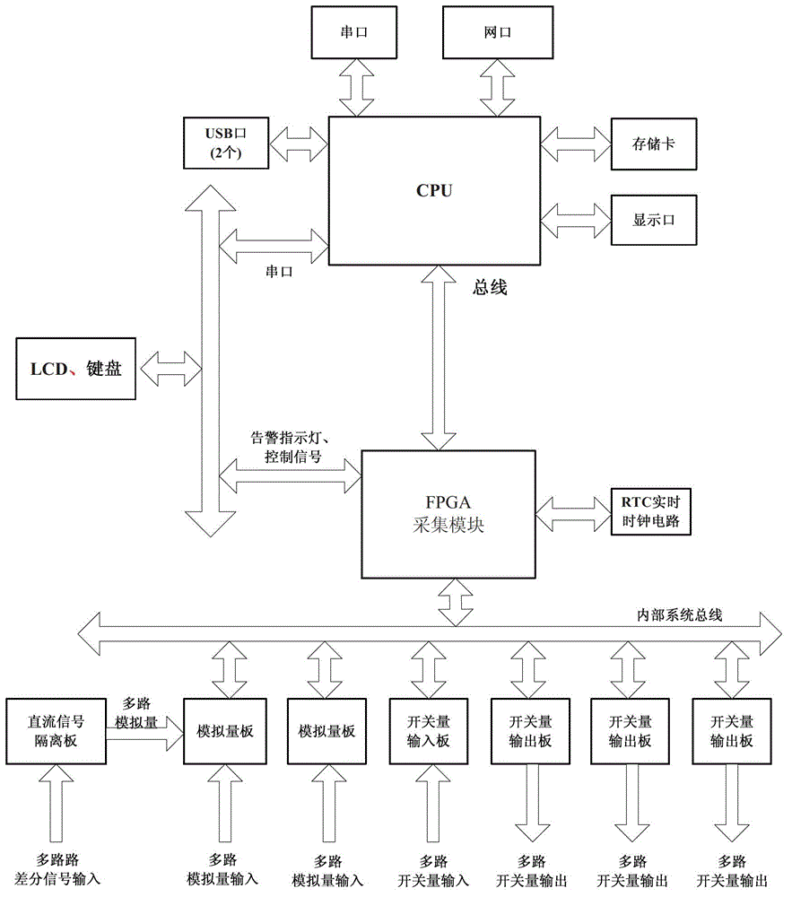
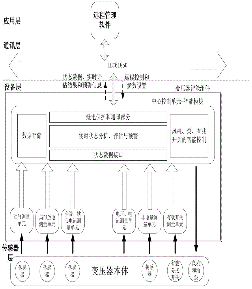
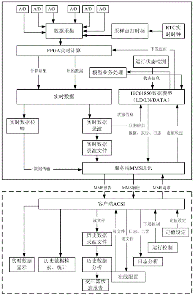
[0084] a kind of like Figure 1~3 The power system transformer integrated monitoring system shown is installed next to the power transformer, including a unified CPU hardware platform based on IEC61850 and a modular design, the corresponding sensors connected to the power transformer to provide various data collection, and the communication protocol with the remote server The software establishes the system terminal for data connection. The system terminal is one of the dispatching terminal and the communication substation PC, and the remote server software is installed. The CPU is used for real-time monitoring and control of the transformer system. It can perform time synchronization, networking and data exchange with the background main server, and can interact with external devices through the display port, memory card, USB port, s...


PUM


Abstract

A comprehensive monitoring system for electric power system transformers comprises an IEC61850-based unified modularized CPU (central processing unit) hardware platform, a sensor, a system terminal, at least one of nine monitoring logical devices, and further comprises an expert analysis system, including a thermal management mathematical model and an oil and gas analysis mathematical model, wherein by configuring and starting software, a function for monitoring corresponding LDs (logical device) which are independent of one another is achieved; and by performing independent effective data acquisition on the transformers respectively, and integrating and processing the data by the CPU, the electric power system transformers are comprehensively monitored in a configurable way. The comprehensive monitoring system for the electric power system transformers is convenient and flexible in application; current situations of repeated data acquisition, and shortage of data integration, data processing, information exchange and information sharing are changed; conversion from the conventional mechanism-based timed maintenance to the state-based preventative maintenance is facilitated; the maintenance cost is obviously saved; service lives of the transformers are prolonged; and a customer can obviously reduce the purchase cost and the management cost.

Description

technical field [0001] The invention relates to transformers, in particular to a comprehensive monitoring system for power system transformers. Background technique [0002] Transformer online monitoring Monitoring is the only way to detect transformer faults early and timely, and realize condition-based preventive maintenance. With the development of smart grid, the online monitoring equipment of transformer will become more and more important. In existing traditional substations, the monitoring devices of high-voltage transformers include many smart devices with different functions. These smart devices are usually provided by different manufacturers and operate independently, which not only increases the purchase cost of users, but also brings a lot Inconvenient, significantly increased management costs. At present, there is no cooling control logic device (Logical Device, abbreviated as LD), winding hot spot temperature measurement LD, electrical quantity recording LD, ...

Claims


Application Information

Patent Timeline
Patent Type & Authority Applications(China)
IPC IPC(8): G01R31/00G01R31/12G01R31/02
Inventor 赵忠黎波彭锦凤
Owner SHENZHEN SHUANGHE ELECTRIC CO LTD
Learn More