Unified power flow controller used for unbalanced system

A technology of power flow controller and converter, applied in flexible AC transmission system, multi-phase network asymmetry reduction, AC network to reduce harmonics/ripples, etc., can solve problems such as limiting large-capacity UPFC applications, and achieve High cost performance, good voltage control ability, good effect of zero sequence current control

Active Publication Date: 2013-03-20
CHINA EPRI SCIENCE & TECHNOLOGY CO LTD +2
View PDF5 Cites 21 Cited by
  • Summary
  • Abstract
  • Description
  • Claims
  • Application Information

AI Technical Summary

Problems solved by technology

These limit the application of large capacity UPFC

Method used


Image

  • Unified power flow controller used for unbalanced system
  • Unified power flow controller used for unbalanced system
  • Unified power flow controller used for unbalanced system

Examples


Embodiment 1

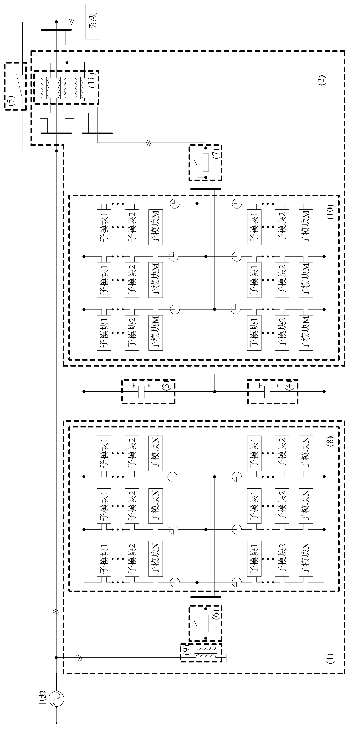
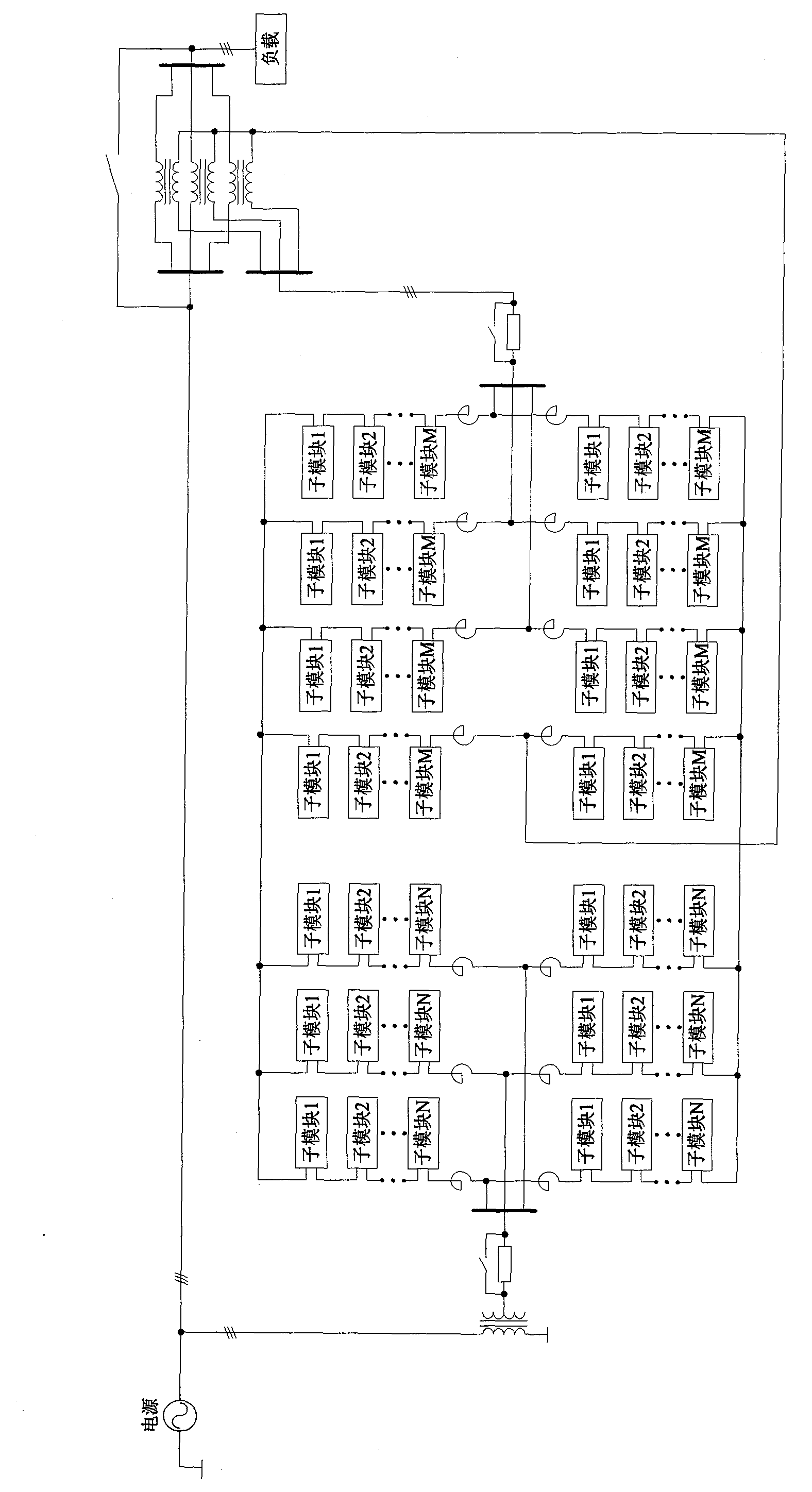
[0051] A three-phase four-wire MMC topology scheme with split capacitors on the series side of a unified power flow controller for an unbalanced system provided by the present invention is as follows image 3 As shown, the unified power flow controller includes a static synchronous compensator 1 and a static synchronous series compensator 2; an upper split capacitor 3 and a lower split capacitor 4 are arranged between the static synchronous compensator 1 and the static synchronous series compensator 2; the upper split The capacitor 3 and the lower split capacitor 4 are connected in series with the static synchronous compensator 1 and the static synchronous series compensator 2 respectively; the upper split capacitor 3 and the lower split capacitor 4 are connected in series to form a split capacitor branch; the midpoint of the split capacitor branch is connected to The neutral point of the series transformer 11 of the static synchronous series compensator 2 is connected; the out...

Embodiment 2

[0066] This embodiment is basically the same as Embodiment 1, but the differences are:

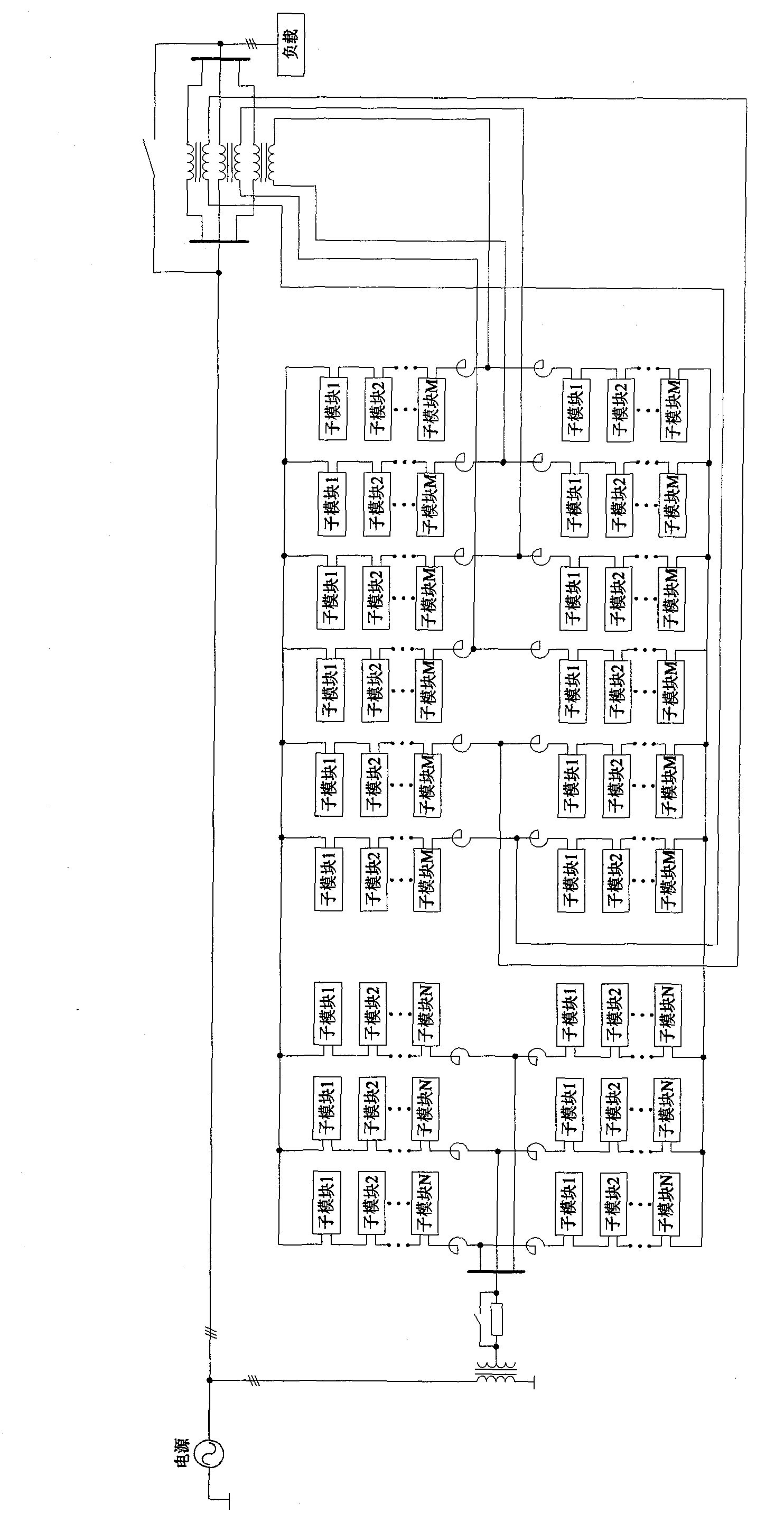
[0067] The locations of the reactors in the inverter 8 and the inverter 10 are different. The reactors in this embodiment are connected in series on the positive and negative bus bars, and are used to suppress the output harmonics of the converter device.

[0068] Specifically, the inverter 8 is composed of three phases; the three phases are connected in parallel; each phase is composed of two upper and lower bridge arms with the same structure in series; Each bridge arm of the upper and lower bridge arms includes a reactor and N sub-modules with the same structure; the sub-modules of each bridge arm are cascaded and one end is connected to the starting circuit 6; the sub-modules of each bridge arm are cascaded The other end of the reactor is connected in series with the reactors of the other two-phase bridge arms to form the positive and negative bus bars of the converter 8 .

[0069] T...


PUM


Abstract

The invention relates to a unified power flow controller used for an unbalanced system. The unified power flow controller comprises a static synchronization compensator and a static synchronization series compensator. An upper part split capacitance and a lower part capacitance are arranged between the static synchronization compensator and the static synchronization series compensator. The upper part split capacitance and the lower part split capacitance are connected in series and then respectively connected with the static synchronization compensator and the static synchronization series compensator in parallel. The upper part split capacitance and the lower part split capacitance are connected in series and then a split capacitance branch circuit is formed. A midpoint of the split capacitance branch circuit is connected with a neutral point of the static synchronization series compensator. Output ends of the static synchronization compensator and the static synchronization series compensator are respectively connected with a power grid. The unified power flow controller is convenient to split-phase control and modularization design, small in running loss, good in voltage control capacity, good in zero-sequence current controlling, few in element quantity, low in cost and high in cost performance.

Description

technical field [0001] The invention relates to a unified power flow controller in the field of flexible alternating current transmission, in particular to a unified power flow controller for an unbalanced system. Background technique [0002] The neutral point of the power grid with a voltage level of 110kV and above adopts a direct grounding method. When the three-phase load is asymmetrical, zero-sequence current will appear on the line. Three-phase voltage unbalance is an important index to measure the power quality of power grid. With the improvement of people's requirements for power quality, the problem of voltage imbalance is receiving more and more attention. In the three-phase system, the causes of voltage imbalance mainly come from two aspects: the output voltage imbalance of the generator and the load asymmetry. Theoretically speaking, the output voltage of the generator is not completely symmetrical and has a certain degree of unbalance, but it should be limite...

Claims


Application Information

Patent Timeline
Patent Type & Authority Applications(China)
IPC IPC(8): H02J3/26H02J3/01
CPCY02E40/16Y02E40/50Y02E40/10Y02E40/40
Inventor 王轩喻劲松闫殳裔李欣武守远何维国
Owner CHINA EPRI SCIENCE & TECHNOLOGY CO LTD
Why Eureka
Try Eureka