Multiway input feedback type electronic load system

An electronic load and multi-input technology, applied in the electronic field, can solve the problems of limited scope of application, low system reliability, and high construction cost, and achieve the effects of saving electronic components, reducing circuit complexity, and expanding the scope of application

Active Publication Date: 2015-03-25
陆东海
View PDF6 Cites 0 Cited by
  • Summary
  • Abstract
  • Description
  • Claims
  • Application Information

AI Technical Summary

Problems solved by technology

[0008] The multi-input feedback electronic load system in the prior art mainly has the following disadvantages: on the one hand, because each branch of the power input under test requires a booster circuit unit, the entire electronic load system has many components and complex circuits. The reliability of the system is low and the construction cost is high; on the other hand, the current and power of each branch input power supply under test will be affected by the switching tube, diode, inductor and other power components of the branch booster circuit unit itself. limit
Since the tolerance range of the power element to the input current and power is smaller than that of the resistance, it is easier to be damaged, thus limiting the scope of application of the power supply under test on the input side of the regenerative electronic load system

Method used


Image

  • Multiway input feedback type electronic load system
  • Multiway input feedback type electronic load system
  • Multiway input feedback type electronic load system

Examples


Embodiment Construction

[0025] The following will clearly and completely describe the technical solutions in the embodiments of the present invention with reference to the drawings in the embodiments of the present invention. Apparently, the described embodiments are only some of the embodiments of the present invention, but not all of them. Based on the embodiments of the present invention, all other embodiments obtained by persons of ordinary skill in the art without creative efforts fall within the protection scope of the present invention.

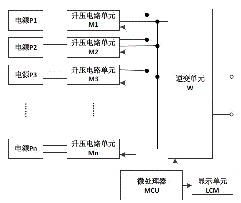
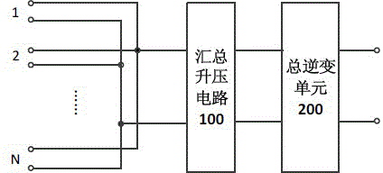
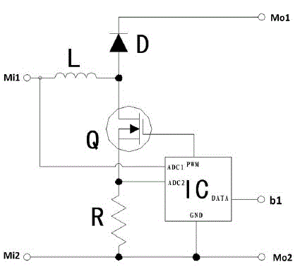
[0026] Combine below Figure 2~Figure 6 , the structure and working principle of the multi-input regenerative electronic load system provided by the embodiment of the present invention will be described in detail.

[0027] see figure 2 , is a structural schematic diagram of the first embodiment of the multi-input regenerative electronic load system provided by the present invention.

[0028] In the first embodiment, the multi-input regenerative electronic...


PUM


Abstract

The invention discloses a multiway input feedback type electronic load system comprising power input ends with a number of N, a summarizing boosted circuit and a total inverter unit, wherein the N is larger than or equal to 2. Each power input end respectively receives a one-way direct-current power signal in a one-one correspondence mode, and transmits the accessed one-way direct-current power signal to a direct current input end of the summarizing boosted circuit. The summarizing boosted circuit works in a constant voltage mode, and the direct-current power signal input by the direct current input end is summarized and then processed in a pressure boost mode. The total inverter unit is connected with a direct-current output end of the summarizing boosted circuit. The total inverter unit is used for converting the direct-current power signal which is processed in a pressure mode by the summarizing boosted circuit to be an alternating current power supply signal. The multiway input feedback type electronic load system is suitable for aging tests of a constant current power source and a constant voltage power source. According to the multiway input feedback type electronic load system, circuit structure is simple, electronic components are greatly reduced, system reliability is high and applicability is wide.

Description

technical field [0001] The invention relates to the field of electronic technology, in particular to a multi-channel input feedback electronic load system. Background technique [0002] There are two main types of off power supplies in terms of output characteristics: constant current power supplies and constant voltage power supplies. [0003] A constant current power supply is a power supply whose output current is constant during normal operation, and its power supply current does not change with the change of the output voltage. For example, if a constant current power supply with a parameter specification of 1A / (0~50V) is connected to any load working in constant voltage mode between 0~50V at the output terminal, the power supply current value will remain at 1A. Correspondingly, a constant voltage power supply is also called a regulated power supply, which requires a fixed output voltage value and does not change with external working conditions such as load and input ...

Claims


Application Information

Patent Timeline
Patent Type & Authority Patents(China)
IPC IPC(8): H02M7/44
Inventor 陆东海王伟雄梁有程
Owner 陆东海
Why Eureka
Try Eureka