Automatic frequency tuning circuit of active resistance-capacitance (RC) filter

An automatic frequency tuning and filter technology, applied in the direction of frequency selection two-terminal-to-network, multi-terminal-to-network, etc., can solve problems such as difficulty in ensuring the accuracy of RC oscillators, limitations of circuit adjustment accuracy, and large tuning circuit area, and achieve good results. Application prospect, simple implementation method, and high tuning accuracy

Active Publication Date: 2013-03-20
CHONGQING SOUTHWEST INTEGRATED CIRCUIT DESIGN
View PDF3 Cites 11 Cited by
  • Summary
  • Abstract
  • Description
  • Claims
  • Application Information

AI Technical Summary

Problems solved by technology

[0004] The existing technology is equivalent to a digital phase-locked loop, and the circuit is relatively complicated. When the oscillation frequency of the RC oscillator is relatively high, there will be errors in the oscillation frequency of the RC oscillator, and it will be difficult to ensure the accuracy of the RC oscillator, making the adjustment of the entire circuit The accuracy is limited; when the RC oscillator is in order to obtain a smaller oscillation frequency, the resistance or capacitance will be larger, so that the area of ​​the tuning circuit will become larger and larger, sometimes even equivalent to the main part of the filter , and its power consumption is relatively large

Method used


Image

  • Automatic frequency tuning circuit of active resistance-capacitance (RC) filter
  • Automatic frequency tuning circuit of active resistance-capacitance (RC) filter
  • Automatic frequency tuning circuit of active resistance-capacitance (RC) filter

Examples


Embodiment Construction

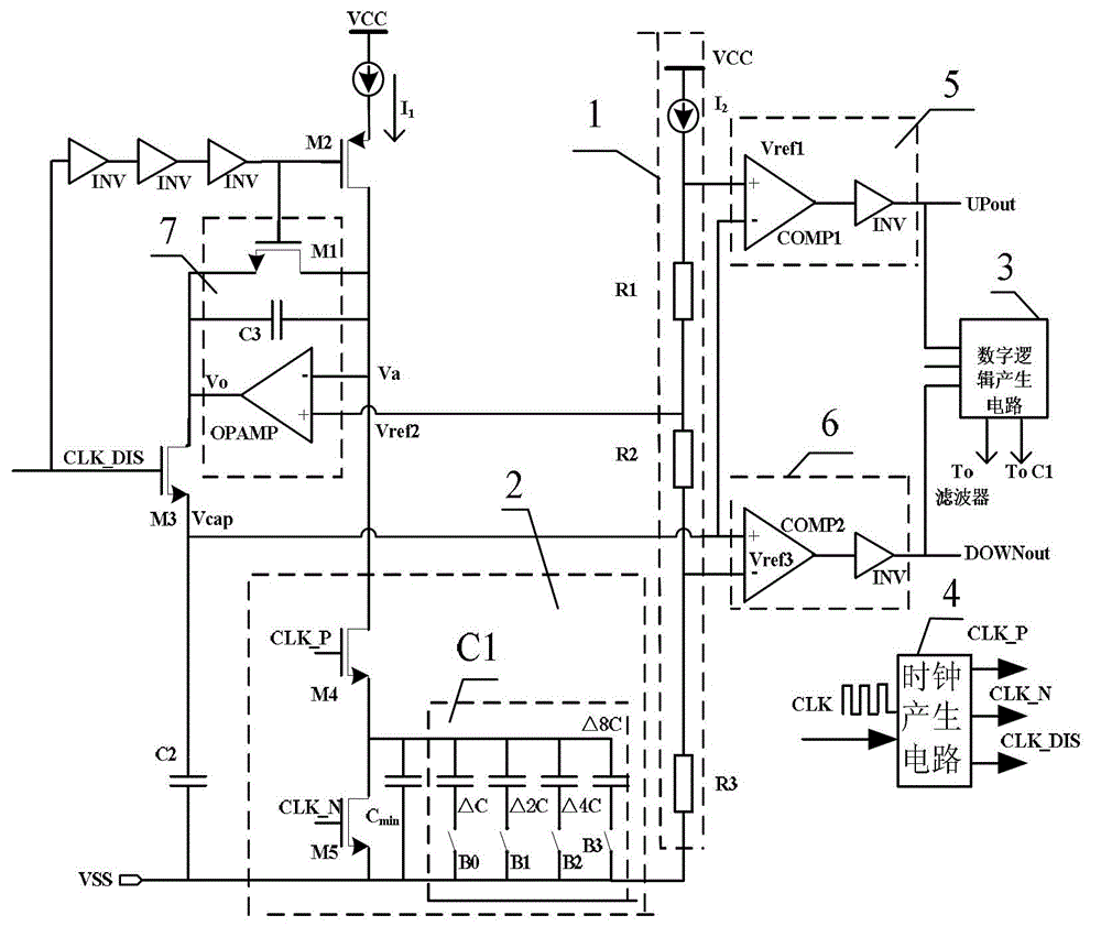
[0023] see image 3 , an active RC filter automatic frequency tuning circuit, including a comparator, a constant current source I1, a reference voltage generating circuit 1, a switched capacitor circuit 2, a digital logic control circuit 3 and a clock generating circuit 4; wherein:

[0024] The reference voltage generation circuit 1 generates a first reference voltage, a second reference voltage and a third reference voltage and inputs them to the first comparator 5, the operational amplifier 7 and the second comparator 6 respectively;

[0025] The switched capacitor circuit 2 includes a capacitor array C1, and the capacitor array C1 adopts the same capacitor array as the filter; the constant current source I1 charges the switched capacitor circuit 2 through the switch tube two, and the switch tube two passes Off is controlled by clock signal one, which is an inverted delay signal of clock signal three; the voltage generated by the constant current source I1 on the switched ca...


PUM


Abstract

The invention discloses an automatic frequency tuning circuit of an active RC filter. The automatic frequency tuning circuit comprises comparators, a constant current source, a reference voltage generating circuit, a switched capacitor circuit and a digital logic control circuit. The automatic frequency tuning circuit is characterized in that the reference voltage generating circuit generates first reference voltage, second reference voltage and third reference voltage which are input to the first comparator, an operational amplifier and the second comparator respectively, voltage generated by the constant current source on the switched capacitor circuit is input to the operational amplifier, and the digital logic control circuit receives signals output by the first comparator and the second comparator, conducts operation treatment, outputs control codes to the switched capacitor circuit and adjusts the equivalent capacitance of the switched capacitor circuit. The automatic frequency tuning circuit is simple in implementation method, low in cost, small in volume, low in power consumption, high in tuning precision, good in application prospect and capable of being widely used in fields such as electronics and communication.

Description

technical field [0001] The invention relates to an active RC filter, in particular to an automatic frequency tuning circuit for an active RC filter. Background technique [0002] Active RC filters can obtain better noise performance, better dynamic range and better linearity, and its implementation method is simple, so it is widely used in zero-IF or low-IF RF receivers. The accuracy and stability of the frequency characteristics of the source RC filter meet the system requirements of the receiver, and the resistance and capacitance values ​​that constitute the filter are required to have sufficient accuracy and stability. However, in the integrated circuit manufacturing process, due to process tolerances It will cause the component parameters to deviate from the design value, and it will also change with the change of the working environment. In general, the ratio of the same type of components in an integrated circuit can be relatively accurate and stable. For example, th...

Claims


Application Information

Patent Timeline
Patent Type & Authority Applications(China)
IPC IPC(8): H03H11/04
Inventor 韦学强范麟唐睿李家祎陈剑万天才徐骅胡维唐景磊刘永光
Owner CHONGQING SOUTHWEST INTEGRATED CIRCUIT DESIGN
Why Eureka
Try Eureka