Airborne small-scale liquid cooling device

A liquid-cooled, small-sized technology, applied in the direction of cooling/ventilation/heating transformation, etc., can solve the problems of not meeting the heat dissipation requirements of electronic equipment, reducing the heat dissipation efficiency of electronic components, unable to use the environmental control liquid cooling system, etc. It is easy to realize and install and use, and the cooling effect is good.

Active Publication Date: 2013-03-20
西安飞豹科技有限公司
View PDF5 Cites 8 Cited by
  • Summary
  • Abstract
  • Description
  • Claims
  • Application Information

AI Technical Summary

Problems solved by technology

[0002] With the continuous development of modern military electronic technology, the heating power of electronic equipment is also increasing, but the volume is becoming smaller and smaller. Those small and compact multi-functional electronic control systems, electronic interference systems, etc. are extremely harmful to heat and pollution. Sensitive, overheating will cause these sensitive electronic and electrical components to fail, the digital display system will display incorrectly, the control system will drift and the system will malfunction when it is lower than the rated load. At present, some old military aircraft and electronic equipment in our country still use natural heat dissipation And air-cooled heat dissipation method, this heat dissipation method not only has low cooling efficiency, but also absorbs dust, oil and other impurities in the air on the surface of electronic components during the test on the ground, which will reduce th

Method used


Image

  • Airborne small-scale liquid cooling device
  • Airborne small-scale liquid cooling device
  • Airborne small-scale liquid cooling device

Examples


Embodiment Construction

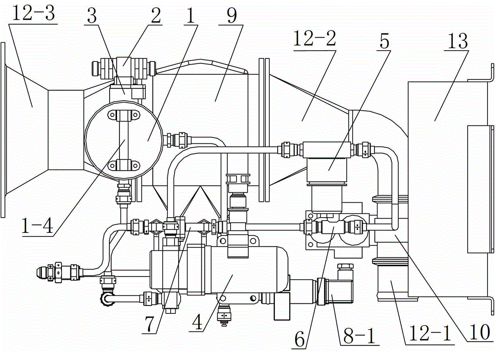
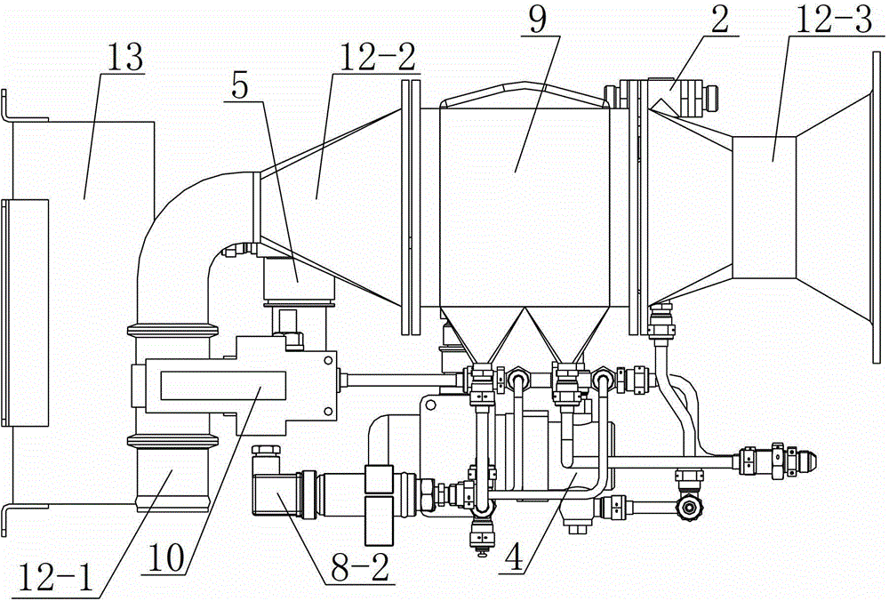
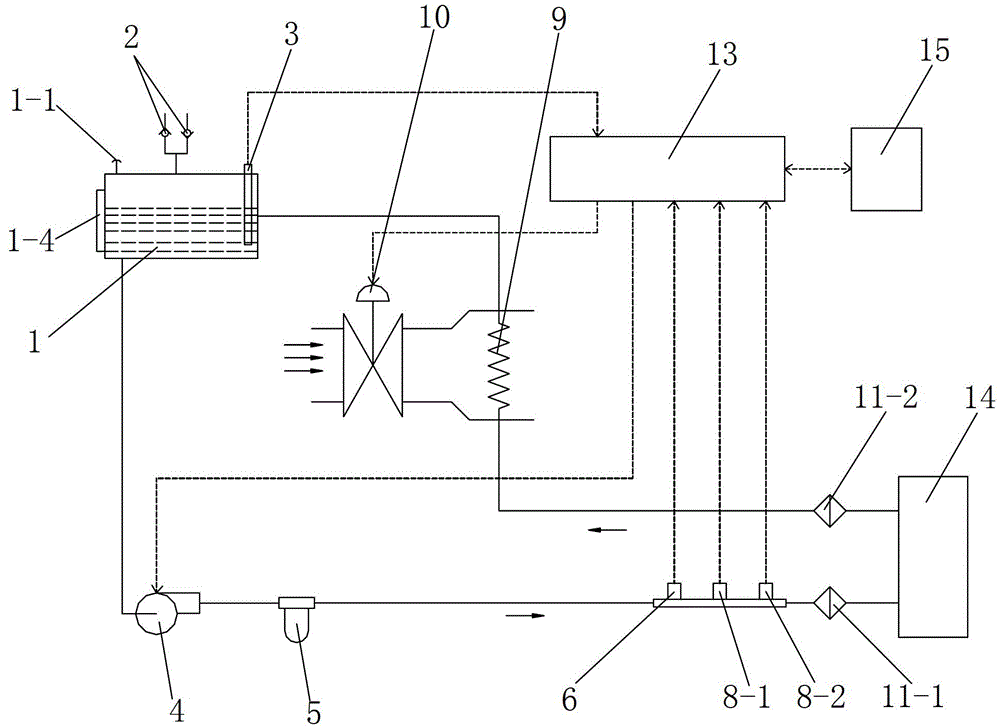
[0048] Such as Figure 1 to Figure 9 As shown, the present invention includes a liquid cooling module and an intelligent control module 13 for collecting and transmitting working parameters of the liquid cooling module in real time and controlling the liquid cooling module. The liquid cooling module includes an expansion tank 1 and a liquid pump 4 , filter 5, flow measuring device 7, gas-liquid heat exchanger 9 and electric valve 10, described liquid pump 4 and electric valve 10 all join with described intelligent control module 13; Described expansion tank 1 is provided with Filling port 1-1, expansion tank liquid inlet pipe seat 1-2 and expansion tank liquid outlet pipe seat 1-3, the liquid pump 4 is provided with a liquid pump liquid inlet pipe seat 4-1 and a liquid pump outlet pipe Seat 4-2, the filter 5 is provided with a filter inlet pipe seat 5-1 and a filter outlet pipe seat 5-2, and the flow measurement device 7 includes a flow measurement tube 7-5 connected to the fl...


PUM


Abstract

The invention discloses an airborne small-scale liquid cooling device which comprises a liquid cooling module and an intelligent control module. The liquid cooling module comprises an expansion tank, a liquid pump, a filter, a flow measuring device, a gas-liquid heat exchanger and an electric valve; a liquid inlet pipe seat of the expansion tank is connected with a liquid outlet pipe seat of the gas-liquid heat exchanger; a liquid outlet pipe seat of the expansion tank is connected with a liquid inlet pipe seat of the liquid pump; a liquid outlet pipe seat of the liquid pump is connected with a liquid inlet pipe seat of the filter; an liquid outlet pipe seat of the filter is connected with a liquid inlet pipe seat of the flow measuring device; a liquid outlet pipe seat of the flow measuring device is connected with airborne electronic equipment to be cooled; a liquid return pipe of the airborne electronic equipment to be cooled is connected with a liquid inlet pipe seat of the gas-liquid heat exchanger; an air inlet of the electric valve is connected with a ram air inlet; an air outlet of the electric valve is connected with an air inlet of the gas-liquid heat exchanger; an air outlet of the gas-liquid heat exchanger is connected with the atmosphere. The airborne small-scale liquid cooling device has the advantages of compact structure, novel and reasonable design, small size, high heat dissipating efficiency, strong universality and good cooling effect.

Description

technical field [0001] The invention relates to a cooling device, in particular to an airborne small liquid cooling device. Background technique [0002] With the continuous development of modern military electronic technology, the heating power of electronic equipment is also increasing, but the volume is becoming smaller and smaller. Those small and compact multi-functional electronic control systems, electronic interference systems, etc. are extremely harmful to heat and pollution. Sensitive, overheating will cause these sensitive electronic and electrical components to fail, the digital display system will display incorrectly, the control system will drift and the system will malfunction when it is lower than the rated load. At present, some old military aircraft and electronic equipment in our country still use natural heat dissipation And air-cooled heat dissipation method, this heat dissipation method not only has low cooling efficiency, but also absorbs dust, oil and...

Claims


Application Information

Patent Timeline
IPC IPC(8): H05K7/20
Inventor 王小军李建民赵鹏涛焦岗黄磊刘延亮
Owner 西安飞豹科技有限公司
Why Eureka
Try Eureka