Dry powder drug delivery system and methods
A dry powder and dry powder inhaler technology, applied in the directions of drug combination, drug formula, drug device, etc., can solve the problems of lack of patient compliance, poor disaggregation, and inconvenient equipment.
- Summary
- Abstract
- Description
- Claims
- Application Information
AI Technical Summary
Problems solved by technology
Method used
Image
Examples
example 1
[0191] Measuring the resistance and flow distribution of a dry powder inhaler-cartridge system
[0192] Several dry powder inhaler designs were tested to measure their resistance to flow, an important characteristic determined in part by the geometry or configuration of the inhaler pathway. Inhalers that exhibit higher resistance require a higher pressure drop to produce the same flow rate as lower resistance inhalers. Briefly, to measure the resistance of each inhaler and cartridge system, various flow rates were applied to the inhaler and the resulting pressure on the inhaler was measured. These measurements can use a vacuum pump attached to the mouth of the inhaler to provide a pressure drop, and a flow controller and pressure gauge to vary the flow and record the resulting pressure. According to Bernoulli's principle, when the square root of pressure drop is plotted against flow velocity, the resistance of an inhaler is the slope of the linear portion of the curve. In th...
example 2
[0199] Measurement of particle size distribution using an inhalation system with insulin preparations
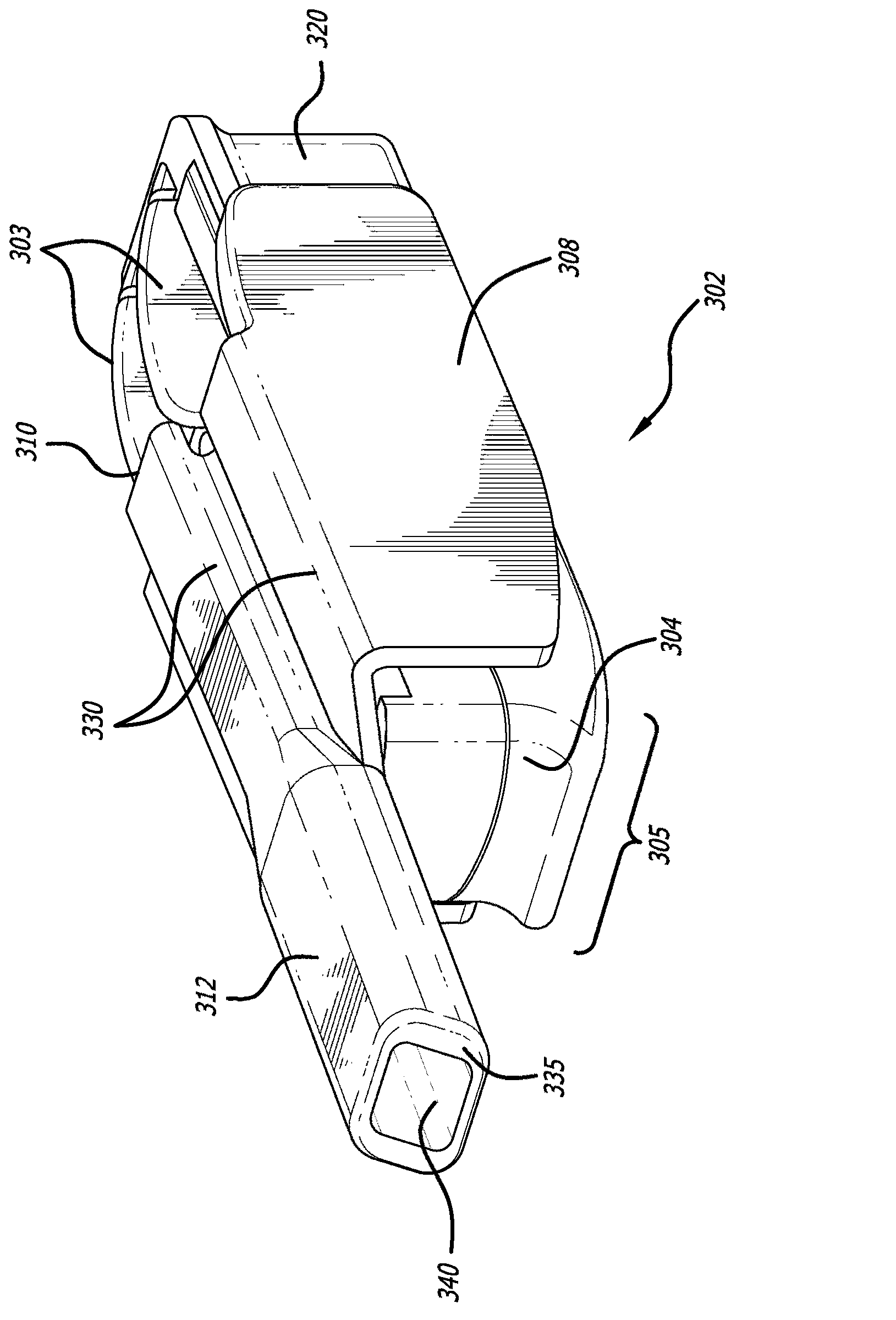
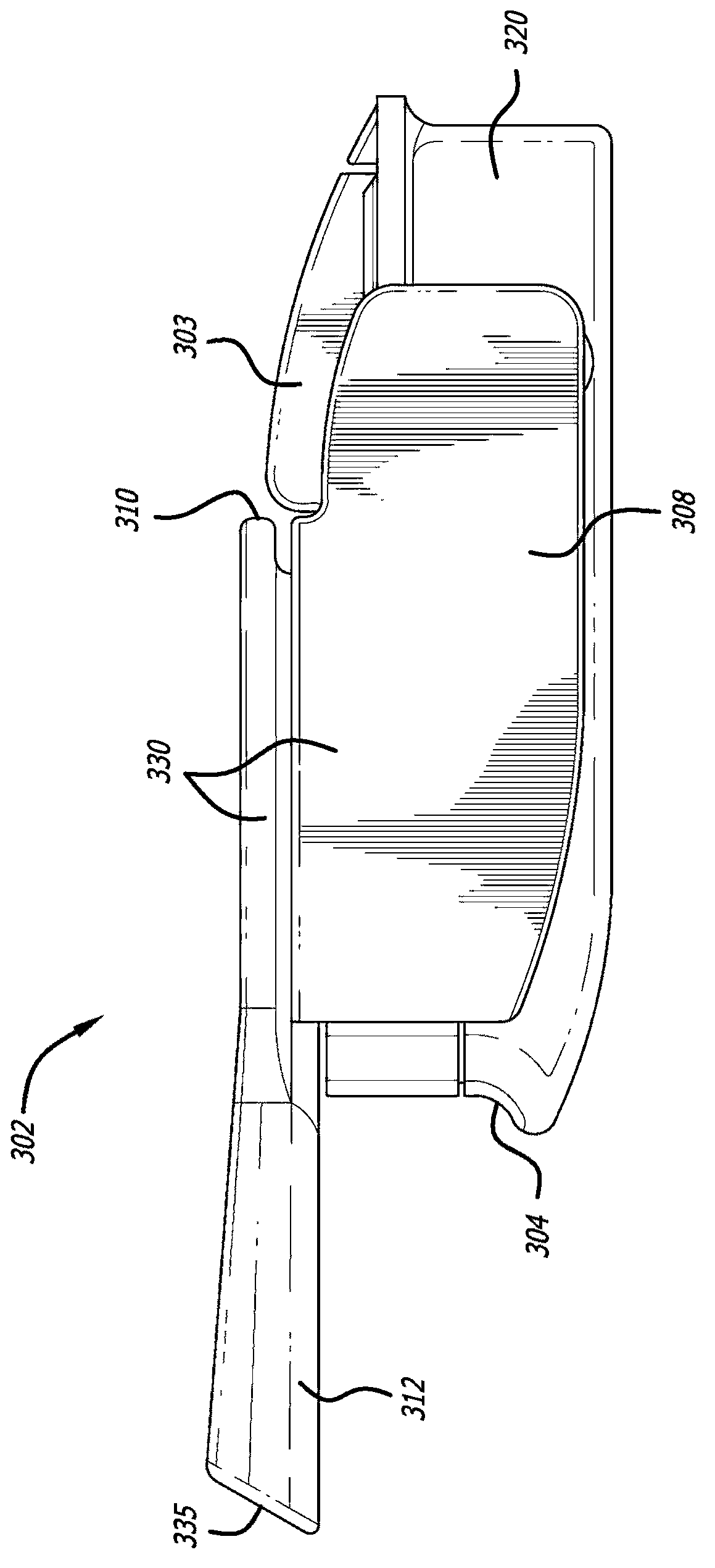
[0200] For the cartridge-inhaler system set as described herein ( Figure 1-9 inhalers and Figure 22-30 Insulin and fumaryl diketopiperazine particles in various amounts (mg) of formulations shown in kit 170) were prepared using adapters (Mannkind Corporation, U.S. Patent Application No. 12 / 727,179, for teachings on related subject matter, The disclosure of this application is hereby incorporated by reference) for the measurement of the particle size distribution by a laser diffraction apparatus (HELOS Laser Diffraction System, Synpatek Corporation). Connect the device at one end to tubing suitable for a flow meter (TSI Corporation, model 4043) and a valve for regulating the pressure or flow rate from a compressed air source. When the laser system is activated and the laser beam is ready to measure the plume, a pneumatic valve is actuated to allow the powder to be expelle...
example 4
[0215] Measurement of Predictive Deposition by Anderson Step Impaction
[0216] Experiments were performed by using Anderson stepped impaction to collect step plate powder deposits during administration of a simulated dose with a flow rate of 28.3 LPM. A flow rate of 28.3 LPM produces a pressure drop of approximately 6 kPa across the inhalation system (DPI+cartridge). The deposits on the stepped plates were analyzed gravimetrically using filters and an electronic balance. For inhaler performance, 10 mg, 6.6 mg and 3.1 mg fill sizes of the cohesive powder were evaluated respectively. Each impaction was performed using 5 cartridges. The amount of accumulated powder collected on Step 2-F was measured in terms of aerodynamic particle size less than 5.8 μm. The proportion of accumulated powder amount relative to the cartridge fill was determined and presented as a percentage of the respirable fraction (RF) relative to the fill weight. The data are shown in Table 4.
[0217] Th...
PUM
| Property | Measurement | Unit |
|---|---|---|
| Particle size | aaaaa | aaaaa |
| Size | aaaaa | aaaaa |
| Density | aaaaa | aaaaa |
Abstract
Description
Claims
Application Information
 - R&D
- Intellectual Property
- Life Sciences
- Materials
- Tech Scout
- Unparalleled Data Quality
- Higher Quality Content
- 60% Fewer Hallucinations
Browse by: Latest US Patents, China's latest patents, Technical Efficacy Thesaurus, Application Domain, Technology Topic, Popular Technical Reports.
© 2025 PatSnap. All rights reserved.Legal|Privacy policy|Modern Slavery Act Transparency Statement|Sitemap|About US| Contact US: help@patsnap.com


