
X-axis ball screw assembly fixture of numerically controlled lathe and method for using X-axis ball screw assembly fixture of numerically controlled lathe

A ball screw and CNC lathe technology, applied in metal processing, manufacturing tools, metal processing equipment, etc., can solve problems such as unstable movement, screw bending, and low efficiency, so as to reduce the impact of production efficiency and improve assembly efficiency , the effect of simple structure

Inactive Publication Date: 2013-03-27
ZHEJIANG RUIYUAN MACHINE TOOL
View PDF4 Cites 6 Cited by
  • Summary
  • Abstract
  • Description
  • Claims
  • Application Information

AI Technical Summary

Problems solved by technology

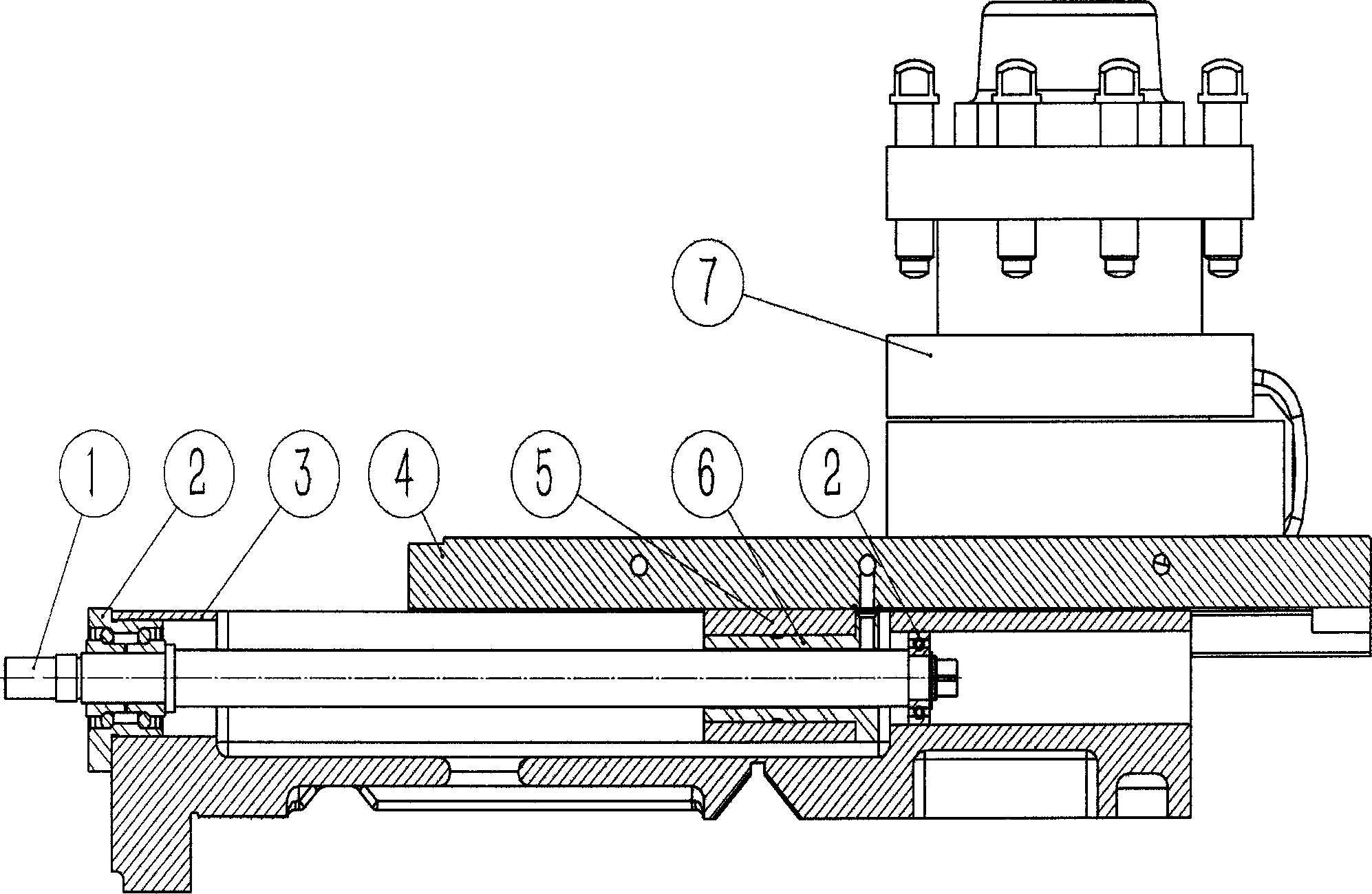
[0003] In the prior art, the assembly of the X-axis ball screw is to add a spacer between the X-axis nut seat and the upper carriage, and to ensure the axis of the X-axis ball screw and the large carriage by measuring and matching the grinding spacer. The planes are parallel, so that firstly, spare parts are added, and the matching strength is not as strong as the direct combination; secondly, due to the insufficient rigidity of the screw, the accuracy of the measured value cannot be guaranteed; thirdly, the operator's proficiency is very high, and at the same time Multiple measurements and matching grinding, the efficiency is not high
Workers assemble the X-axis ball screw based on their experience. The proficiency of the workers has a great influence on the quality of the assembly. If the installation is not done properly, the axis of the screw will bend, and there will be a lot of damage at the front and rear ends of the stroke. Large radial force will cause various faults such as cutting vibration, easy breakage of the screw, out-of-tolerance backlash, unstable movement, unclear lines on the turned end face, and low roughness. In severe cases, the X-axis ball screw will be prematurely broken by fatigue

Method used


Image

  • X-axis ball screw assembly fixture of numerically controlled lathe and method for using X-axis ball screw assembly fixture of numerically controlled lathe
  • X-axis ball screw assembly fixture of numerically controlled lathe and method for using X-axis ball screw assembly fixture of numerically controlled lathe
  • X-axis ball screw assembly fixture of numerically controlled lathe and method for using X-axis ball screw assembly fixture of numerically controlled lathe

Examples


Embodiment Construction

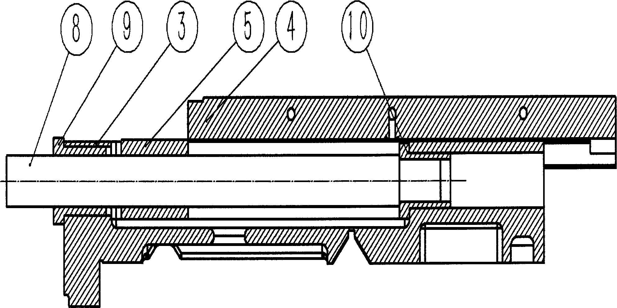
[0016] Such as figure 1 As shown, clean the parts before assembly:

[0017] 1) Install the front guide sleeve (9) and the rear guide sleeve (10) in the holes of the front and rear bearings of the X-axis ball screw on the large pallet (3), and then insert the positioning mandrel (8), The positioning mandrel is penetrated into the X-axis nut seat (5), and the positioning mandrel is required to be able to rotate easily without any gap;

[0018] 2) As large as the measurement of the upper plane of the X-axis nut seat (5) and the joint surface of the upper carriage (4) and the X-axis nut seat is higher than the value, match the grinding of the X-axis nut seat (5), leaving a margin of about 0.2mm carry out scraping;

[0019] 3) Use the surface combined with the X-axis nut seat on the upper carriage (4) to match the upper plane of the X-axis nut seat (5), and the scraping points are required to reach 12-16 points within the range of 25mm×25mm;

[0020] 4) After scraping, take out ...


PUM


Abstract

The invention discloses an X-axis ball screw assembly fixture of a numerically controlled lathe and a method for using the X-axis ball screw assembly fixture of the numerically controlled lathe. The X-axis ball screw assembly fixture comprises a positioning core rod, a front guide sleeve and a rear guide sleeve. The front guide sleeve and the rear guide sleeve are respectively matched with two holes in a large carriage of the numerically controlled lathe for assembling an X-axis ball screw bearing, the diameter of the positioning core rod is matched with a bore of an X-axis nut seat, and the X-axis nut seat penetrates through the positioning core rod to be in directly matched grinding with a plane on an upper carriage, which is linked with the X-axis nut seat. When the X-axis ball screw assembly fixture is used, complicated measuring and match grinding processes can be reduced when operation workers assemble, the assembly reliability of an X-axis ball screw can be ensured, the assembly quality is improved, the influence of the assembling experience of a worker on the production efficiency is reduced, new workers can also quickly master the operation skill, so that the assembly efficiency is effectively improved, the assembly quality of the X-axis ball screw of the numerically controlled lathe can be ensured, and the lathing quality of the numerically controlled lathe can also be greatly improved.

Description

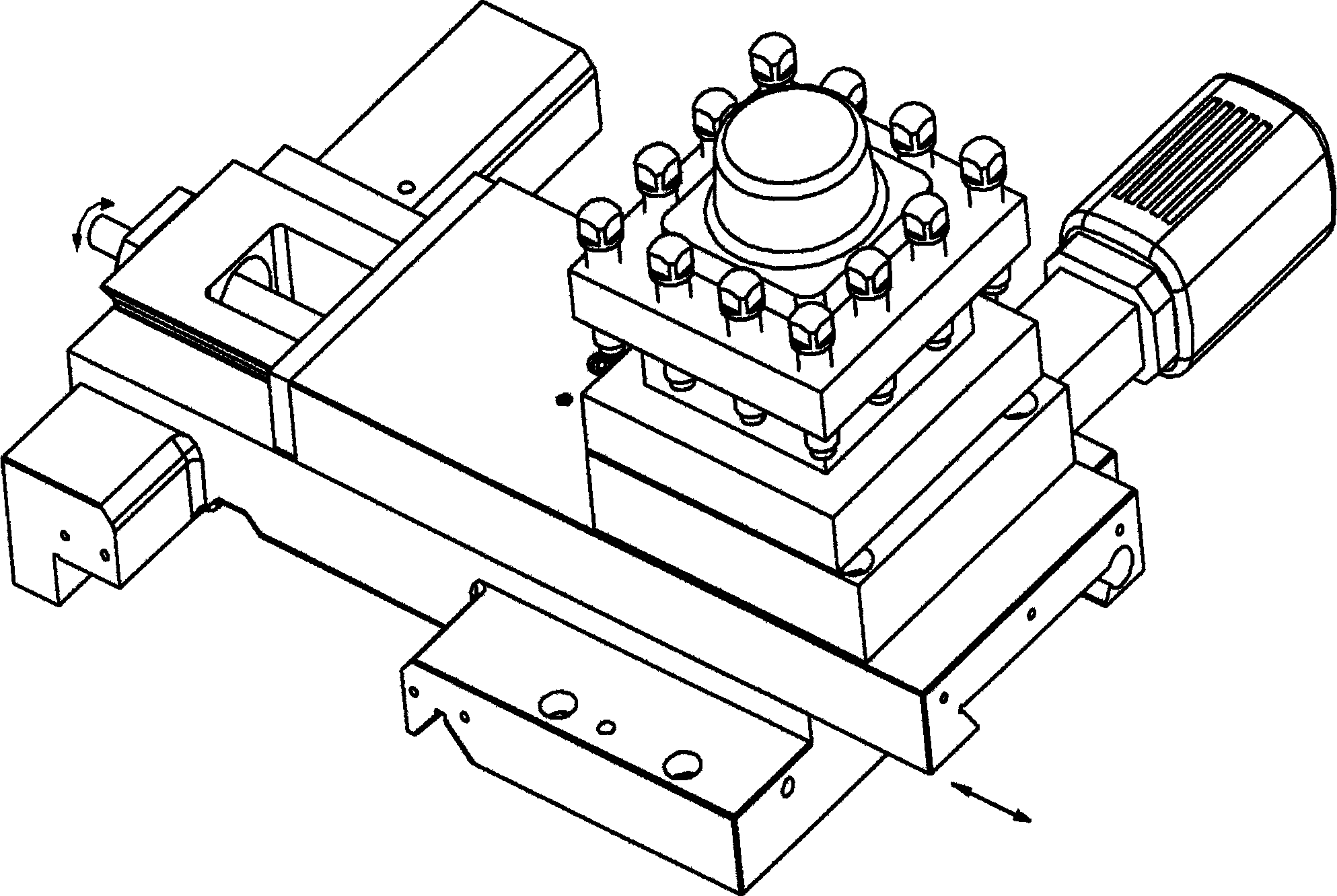
technical field [0001] The invention relates to an assembly tool for an X-axis ball screw of a numerically controlled lathe and a method for using the same. Background technique [0002] The X-axis assembly is one of the important parts of the CNC lathe, which is mainly used to realize the lateral feed movement of the machine tool. The X-axis driving motor drives the X-axis ball screw to rotate through the coupling, and the rotary motion is converted into a linear motion through the ball screw nut, and then the ball screw nut is connected to the ball screw nut through the screw nut seat assembled on the upper carriage to drive The upper carriage moves laterally, thereby realizing the infeed movement of the electric knife rest installed on the upper carriage. Its processing and assembly directly affect the cutting quality of the machine tool, and have a great impact on the performance of the entire machine tool. If the processing and installation are not good, there will be ...

Claims


Application Information

Patent Timeline
Patent Type & Authority Applications(China)
IPC IPC(8): B23P11/00
Inventor 胡为忠
Owner ZHEJIANG RUIYUAN MACHINE TOOL
Learn More