
A collector equipped with a dynamic and static combined sealing structure

A technology of sealing structure and dynamic seal, applied in sealing/isolation, wellbore/well components, earthwork drilling and production, etc., can solve problems such as gas and dust leakage, easy loss of seals, threat to underground safety production, etc., to achieve The effect of reducing friction loss, saving materials, and facilitating normal telescopic movement

Inactive Publication Date: 2015-09-16
HUAIBEI KEAO ENG CONSTR
View PDF6 Cites 0 Cited by
  • Summary
  • Abstract
  • Description
  • Claims
  • Application Information

AI Technical Summary

Problems solved by technology

In the existing devices, the connection sealing structure between the drill hole and the drill pipe of the collector mostly adopts hard seal, soft seal or synchronous rotary sealing technology. The above three sealing methods all have defects in use, such as hard seal will cause the drill pipe and the seal. Strong friction makes the seals easy to wear, and gas and dust leakage occur during use; soft seals are less reliable when encountering high pressure conditions; synchronous rotation sealing technology may generate high heat or sparks during synchronous rotation, which seriously threatens underground safety production

Method used


Image

  • A collector equipped with a dynamic and static combined sealing structure
  • A collector equipped with a dynamic and static combined sealing structure

Examples


Embodiment Construction

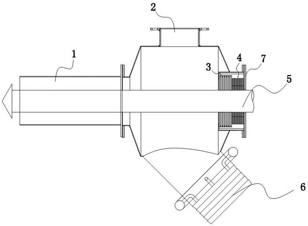
[0015] Such as figure 1 As shown, the collector is connected to the tail end of the borehole pipe 1, and the collector is provided with a gas pumping port 2, a coal and water delivery port 6, and a borehole corresponding to the axial direction of the borehole pipe, and the borehole is from inside to outside A static seal 3 and a dynamic seal 4 are provided in sequence.

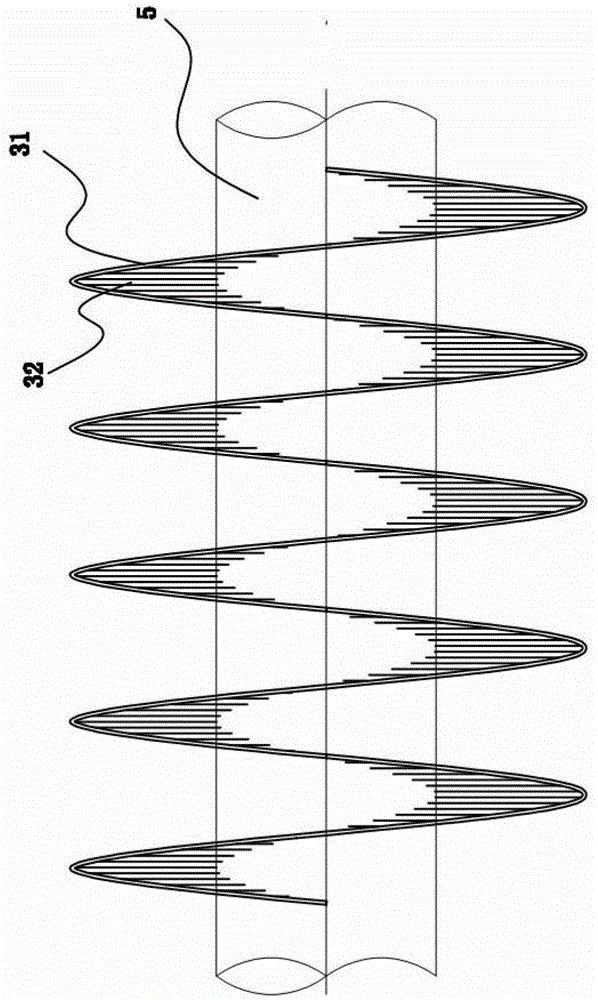
[0016] Such as figure 2 As shown, the main body of the static seal 3 is made of a cylindrical helical ring 31, the inner peripheral wall of the helical ring is covered with bristles 32 in the radial direction, and forms a spiral sealing surface, the length of the bristles is equal and shorter than two of the cylindrical helical rings. One-third of the inner diameter (determined directly according to the drill pipe that needs to pass through); the head of the bristle is attached to the peripheral wall of the drill pipe 5 to form an initial seal.

[0017] The dynamic seal 4 is composed of multiple sealing rin...


PUM


Abstract

The invention discloses a collector provided with a dynamic and static combination sealing structure. The collector is connected at the tail end of a hole protecting pipe and is provided with a gas exhaust port, a coal-gas conveying port and a drilling hole, wherein the drilling hole is axially arranged correspondingly to the hole protecting pipe and a drilling rod can penetrate through the drilling hole. The collector is characterized in that the position of the drilling hole is provided with a static sealing piece and a dynamic sealing piece from inside to outside in sequence; a main body of the static sealing piece is formed by a cylindrical spiral ring; the outer circumferential wall of the spiral ring is in interference fit with the inner wall of the drilling hole; brushing hairs are distributed on the inner circumferential wall of the spiral ring towards the drilling rod along the radial direction to form a spiral sealing surface; the head parts of the brush hairs are attached with the outer circumferential wall of the drilling rod in a contacting manner to form initial seal; the dynamic sealing piece consists of a plurality of sealing rings which are same in size and are distributed in parallel; each sealing ring is in clearance fit with the inner wall of the drilling hole and the outer circumferential wall of the drilling rod in a dynamic manner. The collector can be used for any axial sealing and sealing of a telescopic rod, is especially applied in coal drilling, and has the advantages that not only can the drilling efficiency of the coal seam be improved, but also the stronger safety protection can be provided, and the safe conduction of the coal-seam drilling is ensured.

Description

technical field [0001] The invention relates to a coal drilling collector, in particular to a collector provided with a dynamic and static combined sealing structure. Background technique [0002] For thin and soft coal seams, hydraulic mining is an economical, safe and reliable mining method. However, after water injection fracturing, a large amount of coal, water, and gas will be gushed out through the borehole for subsequent coal, water, and gas separation and induction. Transportation and safety guarantees have become urgent issues. At present, there is no relevant targeted device in China, especially in the sealing of drill pipes, which makes the hydraulic mining of thin and soft coal seams encounter technical bottlenecks. In the existing devices, the connection sealing structure between the drill hole and the drill pipe of the collector mostly adopts hard seal, soft seal or synchronous rotary sealing technology. The above three sealing methods all have defects in use,...

Claims


Application Information

Patent Timeline
Patent Type & Authority Patents(China)
IPC IPC(8): E21B21/015E21B33/06
Inventor 秦小坤陈玲秦晓明田志刚邵凯杜艳秋
Owner HUAIBEI KEAO ENG CONSTR
Learn More