Bearing unit for supporting transmission shaft and gear reducer

A technology of gear reduction and transmission shaft, applied in the direction of rotating bearing, bearing element, shaft and bearing, etc., can solve the problems of false pretension test, larger bearing pair clearance, change of main shaft preload, etc. Achieve the effect of overcoming the illusion of preload, prolonging life and optimizing performance

Inactive Publication Date: 2013-03-27
TIANJIN HUAYE RONGCHENG PRECISION MACHINERY +1
View PDF4 Cites 7 Cited by
  • Summary
  • Abstract
  • Description
  • Claims
  • Application Information

AI Technical Summary

Problems solved by technology

[0011] 1. In order to ensure the pre-tightening force of the main shaft and reasonable clearance control, an adjustment pad is added to the end face of the bearing inner ring and the ring. During the assembly process, it generally needs to go through 2-3 times of test disassembly to meet the process requirements. The assembly process is cumbersome ,low efficiency
[0012] 2. Due to the cumulative error of the parts, there is an illusion in the preload test
[0013] 3. The active bevel gear is limited by space, the distance between the two bearings is small, and the bearing support strength is relatively small
[0014] 4. The high speed at the input end and the large inertial impact when starting and braking will easily increase the clearance of the bearing pair supporting the drive shaft of the reducer and change the pre-tightening force of the main shaft, thereby adversely affecting the meshing of the bevel gear tooth surface. Even cause early wear of the tooth surface

Method used


Image

  • Bearing unit for supporting transmission shaft and gear reducer
  • Bearing unit for supporting transmission shaft and gear reducer
  • Bearing unit for supporting transmission shaft and gear reducer

Examples


Embodiment Construction

[0040] In order to further understand the invention content, characteristics and effects of the present invention, the following examples are given, and detailed descriptions are as follows in conjunction with the accompanying drawings:

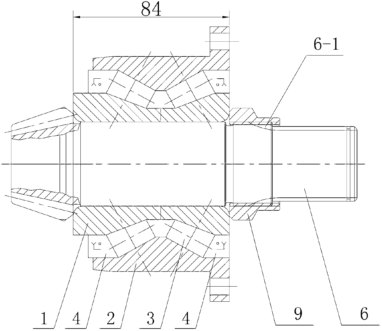
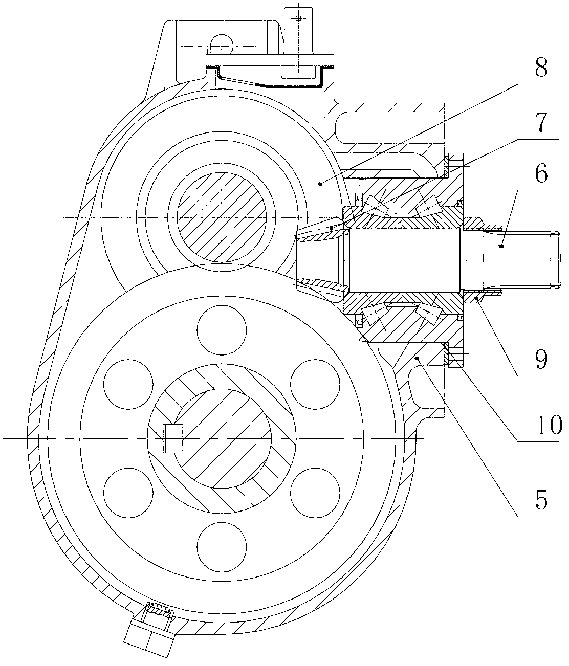
[0041] see Figure 1 to Figure 2 , a bearing unit for supporting a drive shaft, the bearing unit includes an inner ring 1, an outer ring 2 and tapered rollers 3, the tapered rollers 3 adopt two groups, located between the inner ring 1 and the outer ring 2 respectively , the inner ring 1 adopts a split structure, the outer ring 2 adopts a one-piece structure, and a sealing member 4 is provided between the outer ring 2 and the inner ring 1, and the sealing member is different from the existing sealing method The biggest difference is that the existing sealing gland is reduced, and it is directly embedded between the inner ring and the outer ring, so that the structure is more compact, the sealing performance is more reliable, and the manufactur...


PUM


Abstract

The invention relates to a bearing unit for supporting a transmission shaft, which comprises an inner ring, an outer ring, a sealing member, and tapered rollers; two tapered rollers are respectively disposed between the inner ring and the outer ring; the inner ring has a fission structure; the outer ring has an integrated structure; a sealing member is disposed between the outer ring and the inner ring. The invention also relates to a gear reducer which mainly comprises a casing, a transmission shaft, a driving bevel gear, and a driven bevel gear; the transmission shaft is mounted on the casing through the bearing unit; the outer transmission shaft of the bearing unit is equipped with a retaining locking nut. The reducer improves the stability in bevel gear operation, changes traditional assembling methods for obtaining a required bearing clearance by replacing a shim and repeatedly adjusting, omits clearance adjustment, greatly improves the manufacturability and reliability of reducer assembling, reduces complicated process flow for original assembling, and improves production efficiency. In addition, the invention also has the advantages of compact structure, easy mounting and dismounting, and the like.

Description

technical field [0001] The invention belongs to the technical field of supporting bearing components, in particular to a bearing unit and a gear reducer for supporting a transmission shaft. Background technique [0002] As we all know, bearings are generally used to support transmission shafts, and the selection of bearing types is generally carried out according to the actual needs of the equipment, such as support bearings, slewing bearings, thrust bearings, etc. No matter what kind of bearing is in one of the technical parameters is particularly important, that is Clearance, the size of the clearance will affect the transmission accuracy of the transmission shaft. The following is an example of a gear reducer. [0003] When the gear reducer adopts the spiral bevel gear as the first-stage transmission, the transmission shaft is mainly supported by two sets of tapered roller bearings 11, bearing pads 12, adjustment components 13, sealing glands 14, rings 15, bearing sleeve...

Claims


Application Information

Patent Timeline
Patent Type & Authority Applications(China)
IPC IPC(8): F16C19/38F16C33/66F16C33/78F16H57/021F16H57/029
CPCF16C19/386
Inventor 赵家兴李卫
Owner TIANJIN HUAYE RONGCHENG PRECISION MACHINERY
Why Eureka
Try Eureka