Gas burner with stable flame propagation

A technology for gas burners and stable flames, which is applied in the direction of gas fuel burners, burners, and combustion methods, and can solve the problems of small effective working range of burners, large burner volume, and poor combustion stability.

Inactive Publication Date: 2013-03-27
VATTI CORP LTD
View PDF7 Cites 7 Cited by
  • Summary
  • Abstract
  • Description
  • Claims
  • Application Information

AI Technical Summary

Problems solved by technology

The disadvantage of this fire transmission method is that: the combustion speed U1 is greatly affected by environmental factors and the excess air coefficient α, when the gas flow rate U2 is greater than the combustion speed U1, a "flame-off" fault occurs; when the gas flow rate U2 is lower than the combustion speed U1 When there is a "backfire" fault, the combustion state of the gas is greatly affected by the fire transmission speed and the combustion stability is poor
Although the secondary combustion technology effectively prevents the "tempering" problem by reducing the primary air excess coefficient to α≈5, the combustion speed is low, and the burner volume is relatively large under the same heat load requirements, that is, the combustion-to-weight ratio; and the combustion speed adjustment range Narrow and small, the effective working area of ​​the burner is small

Method used


Image

  • Gas burner with stable flame propagation
  • Gas burner with stable flame propagation
  • Gas burner with stable flame propagation

Examples


Embodiment Construction

[0054] Embodiments of the present invention will be described in detail below in conjunction with the accompanying drawings.

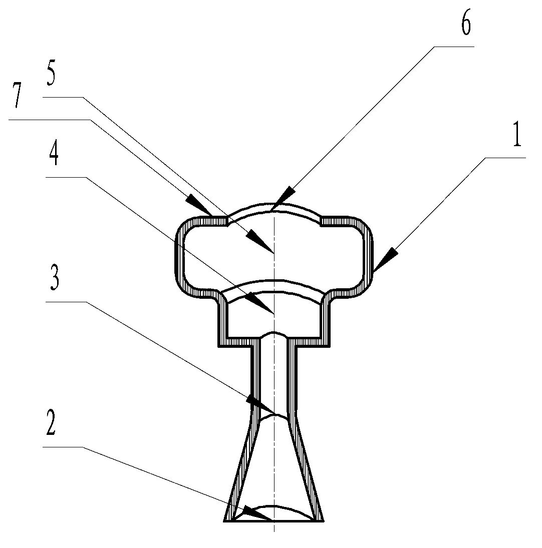
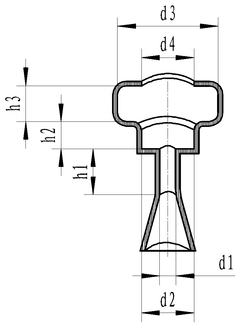
[0055] A gas burner with stable flame propagation in the present invention includes a burner body 1, in that the burner body 1 includes a gas input port 2, a gas nozzle 3, a primary damping diffusion chamber 4 and a combustion chamber 5 connected sequentially from bottom to top The lower end of the gas input port 2 is connected to the gas supply system, the upper end of the combustion chamber 5 is provided with a flame nozzle 6 , and the inner side of the flame nozzle 6 is provided with a vortex block 7 . The diameter of the gas nozzle 3 is d 1 , the diameter of the primary damping diffusion chamber 4 is d 2 , the diameter of combustion chamber 5 is d 3 , the diameter of the flame vent 6 is d 4 , and satisfy d 1 2 3 , d 4 3 .

[0056] The swirl block 7 arranged inside the flame spout 6 on the upper end of the combustion chamber 5 forms an annular...


PUM


Abstract

The invention discloses a gas burner with stable flame propagation. A gas burner body comprises a gas input port, a gas spray pipe, a primary damp diffusion cavity and a combustion chamber, which are sequentially connected from bottom to top, wherein the diameter of the gas spray pipe is d1, the diameter of the primary damp diffusion cavity is d2, the diameter of the combustion chamber is d3, the diameter of a flame nozzle is d4, d2 is more than d1 and less than d3, and the d3 is more than d4. An annular cavity body is formed inside the combustion body through a vortex stopping sheet at the inner side of the flame nozzle at the upper end of the combustion chamber; and flame is combusted inside the annular cavity body, and the section area of the combustion chamber is increased relatively to the primary damp diffusion cavity, so that secondary speed-reduction effect on a fuel speed is realized, the ignition success rate is high and the combustion is stable. Furthermore, a gas pressure has wide application range. The gas burner can stably combust in working modes, such as ultralow-speed atmosphere combustion, low-speed Bunsen type combustion, secondary mixing combustion, turbulent flow type combustion, high-speed full pre-mixing combustion, oxygen supply type ultrahigh-speed combustion and the like. The gas burner has the characteristics of small size, combustion stability, high ignition success rate, large burner thermogravimetrical ratio, and simple structure.

Description

【Technical field】 [0001] The invention relates to a burner, in particular to a gas burner with stable flame propagation. 【Background technique】 [0002] Traditional gas burners generally use the "flame surface" for flame propagation, and the normal flame propagation velocity U1 is usually used to describe the propagation velocity of the "flame surface" in the gas, also known as the combustion velocity. In engineering, combustible mixed gas is used, that is, a mixture of gas and air with an excess air coefficient α≤1, hereinafter referred to as: gas. It flows out of the cold pipe, and the gas flow rate is U2. When U2≤U1, the gas meets the "flame surface" and is ignited to form continuous combustion. The disadvantage of this fire transmission method is that: the combustion speed U1 is greatly affected by environmental factors and the excess air coefficient α, when the gas flow rate U2 is greater than the combustion speed U1, a "flame-off" fault occurs; when the gas flow rate ...

Claims


Application Information

Patent Timeline
IPC IPC(8): F23D14/02F23D14/48F23D14/70F23D14/46
Inventor 黄启均朱铁九
Owner VATTI CORP LTD
Why Eureka
Try Eureka