Plane-based micro-nano object image tilt correction method

A tilt correction, object image technology, applied in the field of image processing, can solve the problem of not being able to accurately reflect the actual situation of the tested sample, etc.

Inactive Publication Date: 2015-06-10
BEIJING INSTITUTE OF TECHNOLOGYGY
View PDF2 Cites 0 Cited by
  • Summary
  • Abstract
  • Description
  • Claims
  • Application Information

AI Technical Summary

Problems solved by technology

In the system that uses a laser scanning microscope to scan and image micro-nano objects, the three-dimensional coordinates of the object are obtained. Using the existing tilt-corrected orientation, the data and images after tilt-correction still cannot accurately reflect the actual situation of the measured sample.

Method used


Image

  • Plane-based micro-nano object image tilt correction method
  • Plane-based micro-nano object image tilt correction method
  • Plane-based micro-nano object image tilt correction method

Examples


Embodiment Construction

[0020] In order to make the purpose, technical solutions and advantages of the embodiments of the present invention clearer, the technical solutions in the embodiments of the present invention will be clearly and completely described below in conjunction with the drawings in the embodiments of the present invention. Obviously, the described embodiments It is a part of embodiments of the present invention, but not all embodiments. Based on the embodiments of the present invention, all other embodiments obtained by persons of ordinary skill in the art without making creative efforts belong to the protection scope of the present invention.

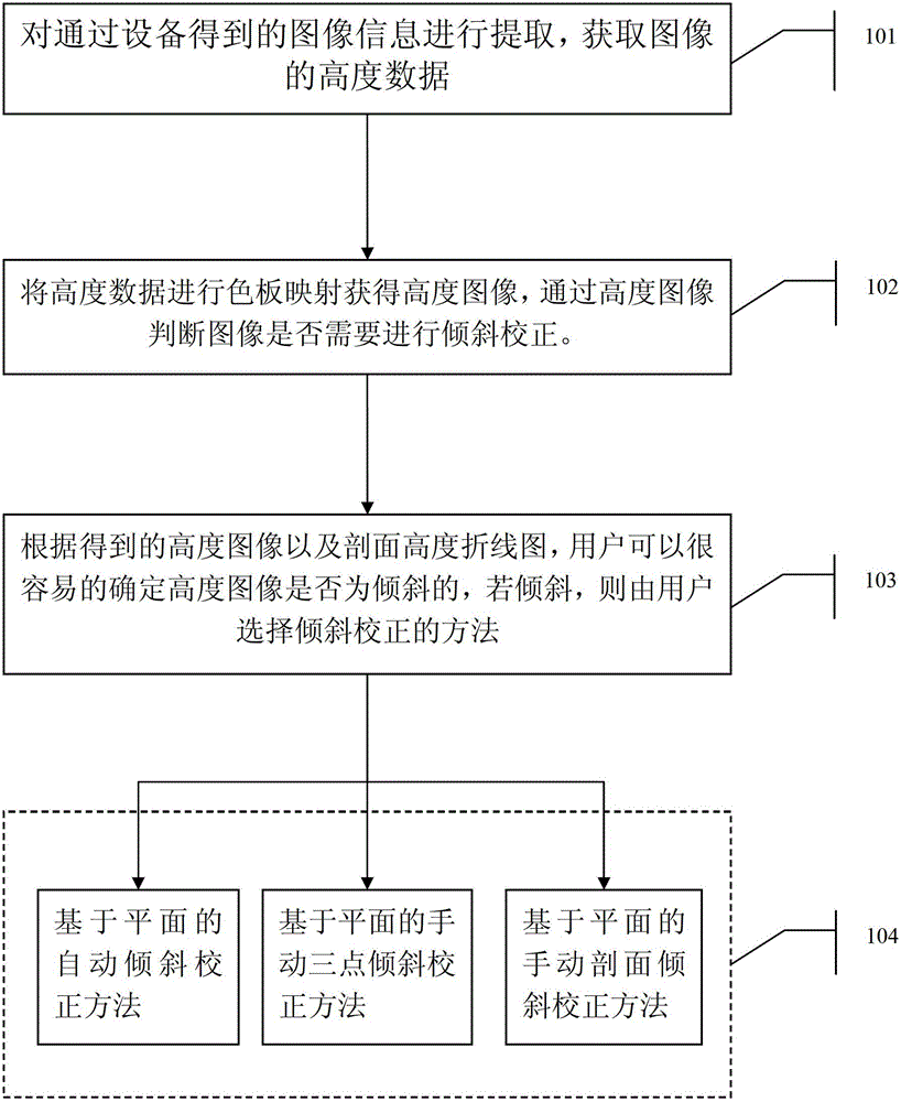
[0021] figure 2 It is a flow chart of an embodiment of the image tilt correction method of the present invention. Such as figure 1 As shown, the image tilt correction method in this embodiment includes:

[0022] Step 101, extract the image information obtained by sampling to obtain height data of the sample to be measured.

[0023] Speci...


PUM


Abstract

The invention relates to a plane-based micro-nano object image tilt correction method. The method includes the steps: subjecting obtained image data to data extraction to obtain height of each point on the upper surface of an object to be measured; allowing a user to determine whether a height image tilts or not and whether the height image needs tilt correction or not; if correction is needed, fitting the measured upper surface into a tilting plane, determining a standard plane, converting height of each point on the surface, to be fitted, to the standard surface in one process, converting the measured height of each point in one process to obtain correction data so as to achieve tilt correction for a micro-nano object three-dimensional image. Z-directional material tilt correction of the micro-nano object three-dimensional image can be effectively achieved by the method, and the obtained image is enabled to more accurately reflect practical conditions of samples measured.

Description

technical field [0001] The invention relates to a tilt correction method for a micro-nano object image, in particular to a plane-based tilt correction method for a micro-nano object image, which belongs to the technical field of image processing. Background technique [0002] Laser scanning microscope is a new type of scanning imaging system based on optical microscope and various scanning microscopes. The focused laser beam is used to scan the surface of the sample, and the photoelectric detection device is used to receive the reflected light (or transmitted light) of the sample. The change of the sample structure changes the intensity of the reflected light (or transmitted light), thus changing the output current of the photodetector. After signal processing, it is displayed on the computer screen synchronously. [0003] Since the sample to be tested is a micro-nano object, the sample to be tested is often tilted due to unequal placement during sampling. In order to accu...

Claims


Application Information

Patent Timeline
Patent Type & Authority Patents(China)
IPC IPC(8): G06T7/00
Inventor 金福生安婧雯宋红
Owner BEIJING INSTITUTE OF TECHNOLOGYGY
Why Eureka
Try Eureka