Quantum cryptography network dynamic routing method

A quantum cryptography and routing technology, which is applied in the communication field of quantum cryptography network, and can solve the problems of frequent state changes of quantum cryptography network path, restricted, consumption of quantum keys, etc.

Active Publication Date: 2013-03-27
SHANDONG INST OF QUANTUM SCI & TECH +2
View PDF6 Cites 58 Cited by
  • Summary
  • Abstract
  • Description
  • Claims
  • Application Information

AI Technical Summary

Problems solved by technology

[0016] 3. The encryption mechanism of the quantum cryptography network needs to consume a large number of keys. Sometimes the key consumption speed is much faster than the generation speed. The path of the quantum cryptography network will be in an unusable state due to insufficient quantum keys at both ends of the path. Network, the path status of quantum cryptography network often changes frequently
[0019] Chinese Patent No. 201010144106.0 discloses "a quantum router for a multi-user optical quantum communication network and its routing method". Does not consider whether the amount of quantum keys on the communication path is sufficient
However, this patent solution has two disadvantages: first, the overall routing path selected by this patent solution may not be the shortest path; The encryption capability of a hop path with the lowest encryption capability is lower than that of another optional overall routing path, and the encryption capability of a path is often subject to the encryption capability of the hop path with the lowest encryption capability
[0020] The above patents related to quantum cryptography network routing do not provide a complete solution for dynamic routing of quantum cryptography networks, that is, how to transmit communication data from the initial node to the destination node through the selection of relay nodes according to the change of the topology state of the quantum cryptography network. Guaranteed communication security while consuming fewer quantum keys

Method used


Image

  • Quantum cryptography network dynamic routing method
  • Quantum cryptography network dynamic routing method
  • Quantum cryptography network dynamic routing method

Examples


Embodiment Construction

[0095] Below in conjunction with accompanying drawing and embodiment the present invention will be further described:

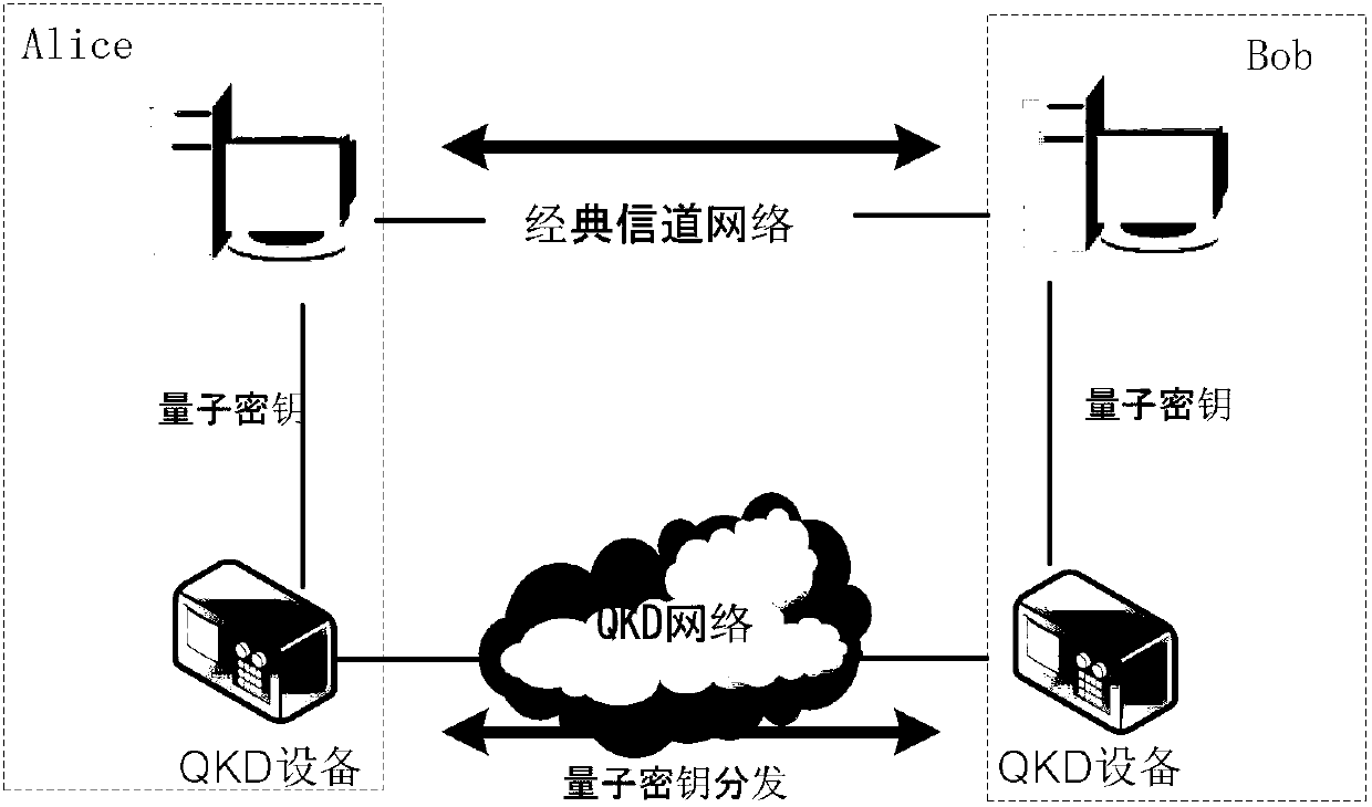
[0096] This embodiment is aimed at a metropolitan quantum cryptography network with thousands of terminal nodes and less than 100 relay nodes. The relay node of this metropolitan area network is a quantum centralized control station, and the centralized control station generally directly connects several terminal nodes or connects several terminal nodes through the optical switch 5 . attached Figure 4 It is a partial schematic diagram of the metropolitan area quantum cryptography network. The first quantum centralized control station 1 and the second quantum centralized control station 2 directly connect to the terminal nodes, the fourth quantum centralized control station 4 connects to the terminal nodes through the optical switch 5, and the third quantum centralized control station The control station 3 directly connects to the terminal node and at the sa...


PUM


Abstract

The invention discloses a quantum cryptography network dynamic routing method. According to the method, dynamic routing selection of encryption communication is performed by utilizing quantum cryptography according to changes of the quantum key quantity between relay nodes of a quantum cryptography network. According to the method, a route server is arranged for the relay nodes of the whole quantum cryptography network, and topology refresh cycles of the quantum cryptography network are set; in each topology refresh cycle, each relay node collects and processes state information of the relay node and reports results to the route server. After the route server collects the topology state information of each relay node, quantum cryptography network topology state information of a next topology refresh cycle is generated and sent to all the relay nodes of the quantum cryptography network. According to the quantum cryptography network topology state information obtained from the route server, a target relay node is calculated and determined to be a next skip route of communication data of a random other relay node according to a shortest path law through each relay node.

Description

technical field [0001] The invention relates to the communication field of a quantum cryptography network constructed by a quantum communication network and a classical communication network, in particular to a dynamic routing method for a quantum cryptography network. Background technique [0002] Quantum communication is a new interdisciplinary subject developed in the past two decades, and a new research field combining quantum theory and information theory. Recently, this subject has gradually moved from theory to experiment, and to practical development. Efficient and secure information transmission has attracted increasing attention. [0003] Physically, quantum communication can be understood as high-performance communication realized by using quantum effects under the physical limit. In informatics, we believe that quantum communication is the use of the basic principles of quantum mechanics (such as the principle of non-cloning of quantum states and the measuremen...

Claims


Application Information

Patent Timeline
Patent Type & Authority Applications(China)
IPC IPC(8): H04L12/733H04L9/08H04L45/122
Inventor 原磊黄勇赵梅生武宏宇赵勇
Owner SHANDONG INST OF QUANTUM SCI & TECH
Why Eureka
Try Eureka