Display, in particular head-up-display of a vehicle

A head-up display and display technology, which is applied to the arrangement of instruments and instruments, optics, etc., can solve the problems of increasing light sources, low transmission, unfavorable information visualization, etc., and achieve the effect of small light loss and high contrast

Inactive Publication Date: 2013-03-27
JOHNSON CONTROLS TECH CO
View PDF6 Cites 23 Cited by
  • Summary
  • Abstract
  • Description
  • Claims
  • Application Information

AI Technical Summary

Problems solved by technology

Disadvantageously, HUDs such as these have relatively low brightness and contrast due to the relatively low transmissivity of LCDs
Therefore, it is not conducive to the visualization of information for the driver or pilot
Furthermore, since a strong light source generates a lot of heat, the lower transmission cannot be compensated simply by increasing the light intensity of the light source, making a relatively complex and expensive cooling mechanism required in this case to cool the display

Method used


Image

  • Display, in particular head-up-display of a vehicle

Examples


Embodiment Construction

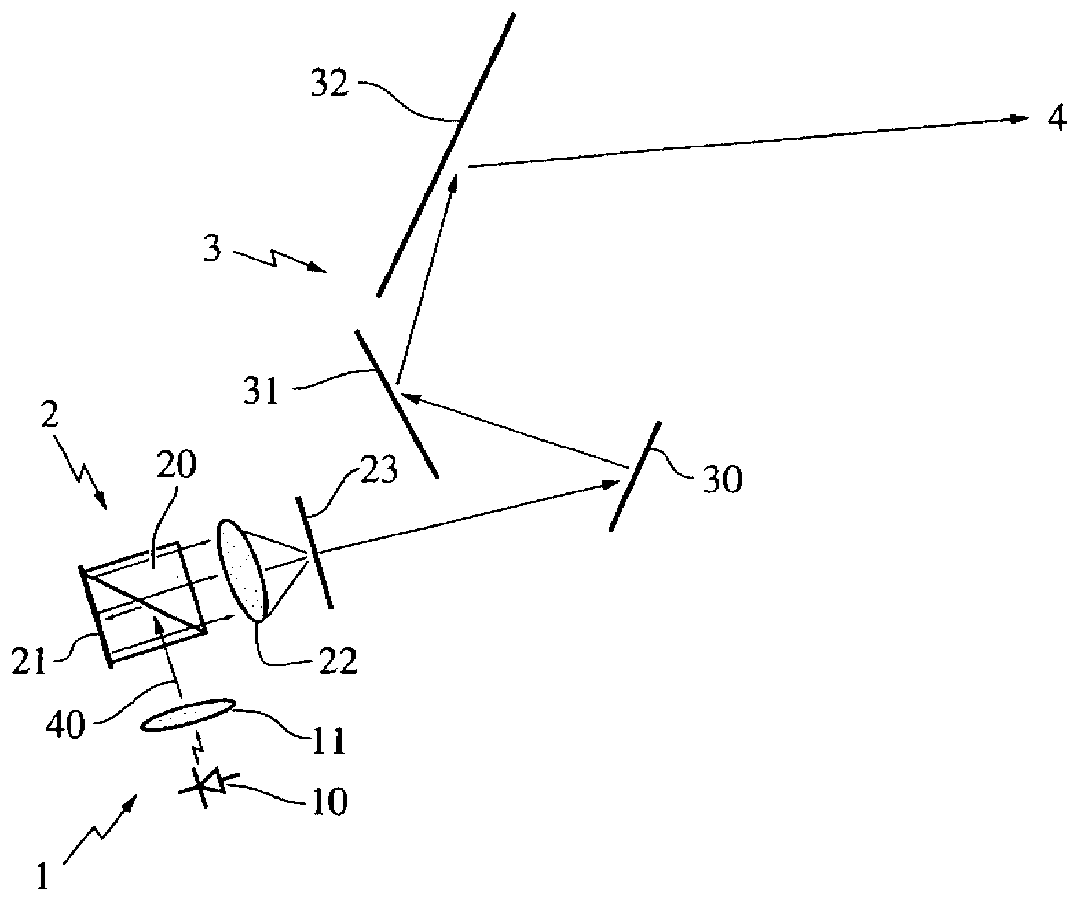
[0018] figure 1 A head-up display according to an exemplary embodiment of the present invention is shown. The head-up display includes an illumination module 1 , an image forming unit 2 and a deflection unit 3 . The lighting module 1 comprises at least one light source 10 and a light collimating optical element 11, wherein the light source 10 is configured as an LED or a laser according to the present invention. The light source 10 emits light having a first wavelength or wavelengths having a first wavelength range. The light collimating optical element 11 substantially collimates the light emitted by the light source 10 into a single beam 40 such that the light from the light source 10 leaves the lighting module 1 as a single beam 40 with substantially parallel light paths. In this example, the light-collimating optical element 11 comprises a condenser lens.

[0019] The polarizing beam splitter 20 of the image forming unit 2 at least partially reflects the light beam 40 a...


PUM


Abstract

The present invention relates to a display, in particular Head-Up-Display of a vehicle, comprising an image forming unit for generating an image, an illumination means for illuminating the image forming unit and a deflecting unit for providing a user with a virtual image of the image generated by the image forming unit, wherein the image forming unit comprises a reflective LCoS- (Liquid Crystal on Silicon) display and the deflecting unit comprises a partially transmissive combiner.

Description

technical field [0001] The invention relates to a display, in particular a head-up display of a vehicle, comprising an image forming unit for generating an image, an illumination module for illuminating the image forming unit, and The deflection unit of the virtual image of the image. Background technique [0002] Head-up displays such as this are known from the prior art. Head-up displays as described above have been used for several years in aircraft cockpits and motor vehicles in order to provide pilots or drivers with information such as aircraft or vehicle operating data in a comfortable manner. For this purpose, head-up displays using monochrome visual imaging are mostly used. At the same time, there is an ever-increasing amount of information that must be provided to the pilot or driver, so the clearest and most detailed visualization is required. This can advantageously be achieved by a multicolor visualization of the information. In this way, for example, warnin...

Claims


Application Information

Patent Timeline
Patent Type & Authority Applications(China)
IPC IPC(8): G02B27/01
CPCG02B27/283G02F1/136277G02B2027/011G02F1/133553G02F1/133528G02B2027/0112G02F1/1313G02B5/30G02B27/0101B60K37/02G02F1/13355
Inventor B·路德维希S·埃尔维
Owner JOHNSON CONTROLS TECH CO
Why Eureka
Try Eureka