Copper rod polishing machine

A polishing machine and copper rod technology, applied in the field of polishing machines, can solve problems such as low friction efficiency, uneven layout of copper rods, affecting processing quality, etc., and achieve the effect of improving processing quality and high polishing efficiency

Inactive Publication Date: 2013-04-03
常熟中佳新材料有限公司
View PDF7 Cites 15 Cited by
  • Summary
  • Abstract
  • Description
  • Claims
  • Application Information

AI Technical Summary

Problems solved by technology

[0002] In the production of copper wires, the copper rods are generally drawn into thinner wires gradually through the process of large drawing and medium drawing through wire drawing wheels. Since the raw materials of copper rods are in the drawing process, the shape of the copper rods is roughly round, so through It is difficult to ensure the uniform and smooth appearance of the copper rod by direct wire drawing, which will affect the subsequent processing quality
In order to make the surface of the copper rod meet the quality requirements, it is generally polished. The existing polishing methods include mechanical polishing and chemical polishing. Mechanical polishing generally adopts the method of grinding. For the surface polishing of flat products, the existing polishing machine has Many types, and the existing polishing method for the surface polishing of cylindrical materials is only static grinding with polishing wheels, so it is not conducive to ensuring the cylindricity of cylindrical material contours
Th

Method used


Image

  • Copper rod polishing machine
  • Copper rod polishing machine
  • Copper rod polishing machine

Examples


Embodiment Construction

[0027] The principles and features of the present invention are described below in conjunction with the accompanying drawings, and the examples given are only used to explain the present invention, and are not intended to limit the scope of the present invention.

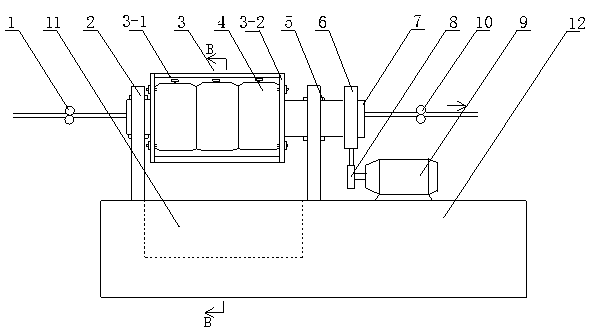
[0028] Such as Figure 1 to Figure 4 As shown, a copper rod polishing machine includes a body 12, a rotating cage 3 and a geared motor 9, the body 12 is provided with a support 2, and the two ends of the rotating cage 3 are respectively provided with a hollow shaft 7, and the support The upper end of 2 is connected with the hollow shaft 7 through the bearing 5, and the hollow shaft 7 at one end of the basket 3 is provided with a pulley 6, and the pulley 6 is connected with the output pulley 8 of the reduction motor 9 through a belt , One or more polishing discs 4 are arranged on the rotating cage 3, and the center of the polishing discs 4 is provided with a wire passing hole 4-1.

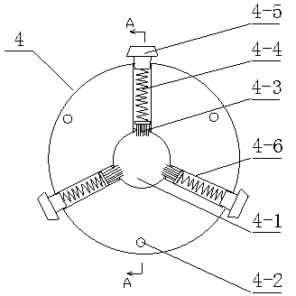
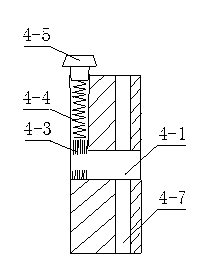
[0029] The polishing disc 4 inclu...


PUM


Abstract

The invention relates to a copper rod polishing machine, which comprises a machine body, a rotary cage and a speed reduction motor, wherein the machine body is provided with a support. The copper rod polishing machine is characterized in that the two ends of the rotary cage are respectively provided with a hollow rotating shaft; the upper end of the support is connected with the hollow rotating shaft through a bearing; the hollow rotating shaft at one end of the rotary cage is provided with a belt wheel; the belt wheel is connected with an output belt wheel of the speed reduction motor through a belt; the rotary cage is provided with a polishing disk or a plurality of polishing disks; and the center of the polishing disk is provided with a wire passing hole. The copper rod polishing machine has the beneficial effects that as the rotary cage and a polishing disk structure are adopted, a rotatable polished wire passing hole is formed in the rotary cage; when wire rods or copper rods pass through the wire passing hole, the materials such as copper rods are polished in all directions; and compared with static polishing of a polishing head in the prior art, the materials such as copper rods can reach good cylindrical degree, so that the polishing efficiency and quality can be greatly improved.

Description

technical field [0001] The invention relates to the technical field of polishing machines, in particular to a copper rod polishing machine. Background technique [0002] In the production of copper wires, the copper rods are generally drawn into thinner wires gradually through the process of large drawing and medium drawing through wire drawing wheels. Since the raw materials of copper rods are in the drawing process, the shape of the copper rods is roughly round, so through It is difficult to ensure the uniform and smooth appearance of the copper rod by direct wire drawing, which will affect the subsequent processing quality. In order to make the surface of the copper rod meet the quality requirements, it is generally polished. The existing polishing methods include mechanical polishing and chemical polishing. Mechanical polishing generally adopts the method of grinding. For the surface polishing of flat products, the existing polishing machine has There are many type...

Claims


Application Information

Patent Timeline
IPC IPC(8): B24B29/08B24B55/06
Inventor 李家亭袁光兵
Owner 常熟中佳新材料有限公司
Why Eureka
Try Eureka