Brake-by-wire system of automobile

A technology of braking system and automobile line, applied in the direction of brakes, brake transmission devices, vehicle components, etc., can solve the problems of total braking force, adverse effects of feedback braking force, inconvenient installation and arrangement, hidden dangers, etc., and achieve structural improvement. Small size, high pressure control accuracy, and the effect of reducing potential safety hazards

Active Publication Date: 2013-04-03
TSINGHUA UNIV
View PDF7 Cites 38 Cited by
  • Summary
  • Abstract
  • Description
  • Claims
  • Application Information

AI Technical Summary

Problems solved by technology

A disadvantage of this type of system is that the high pressure maintained in the accumulator is a safety hazard, and in the event of a collision the accumulator becomes a "cannonball" that poses a threat to the occupants
The disadvantage of this solution is: the piston in the first chamber of the master cylinder controlled by the motor cannot move backwards at the initial position to decompress. When the braking strength is relatively small and the regenerative braking can independently meet the braking strength requirements, driving The operator depresses the brake pedal and pushes the plunger in the first cavity piston of the master cylinder to move forward to establish a certain brake hydraulic pressure, which should be reduced, but because the piston of the first cavity of the master cylinder controlled by the motor The position moves backward to implement decompression, so it will have a negative impact on the total braking force and regenerative braking force
The scheme of using brake fluid is represented by Delphi Corporation and DEHB of Tsinghua University. The brake actuator can be placed above the suspension, and the working environment is greatly improved. However, the distributed structure is not as good as that of the traditional brake system. Big change, there is some inconvenience in installation and layout

Method used


Image

  • Brake-by-wire system of automobile

Examples


Embodiment Construction

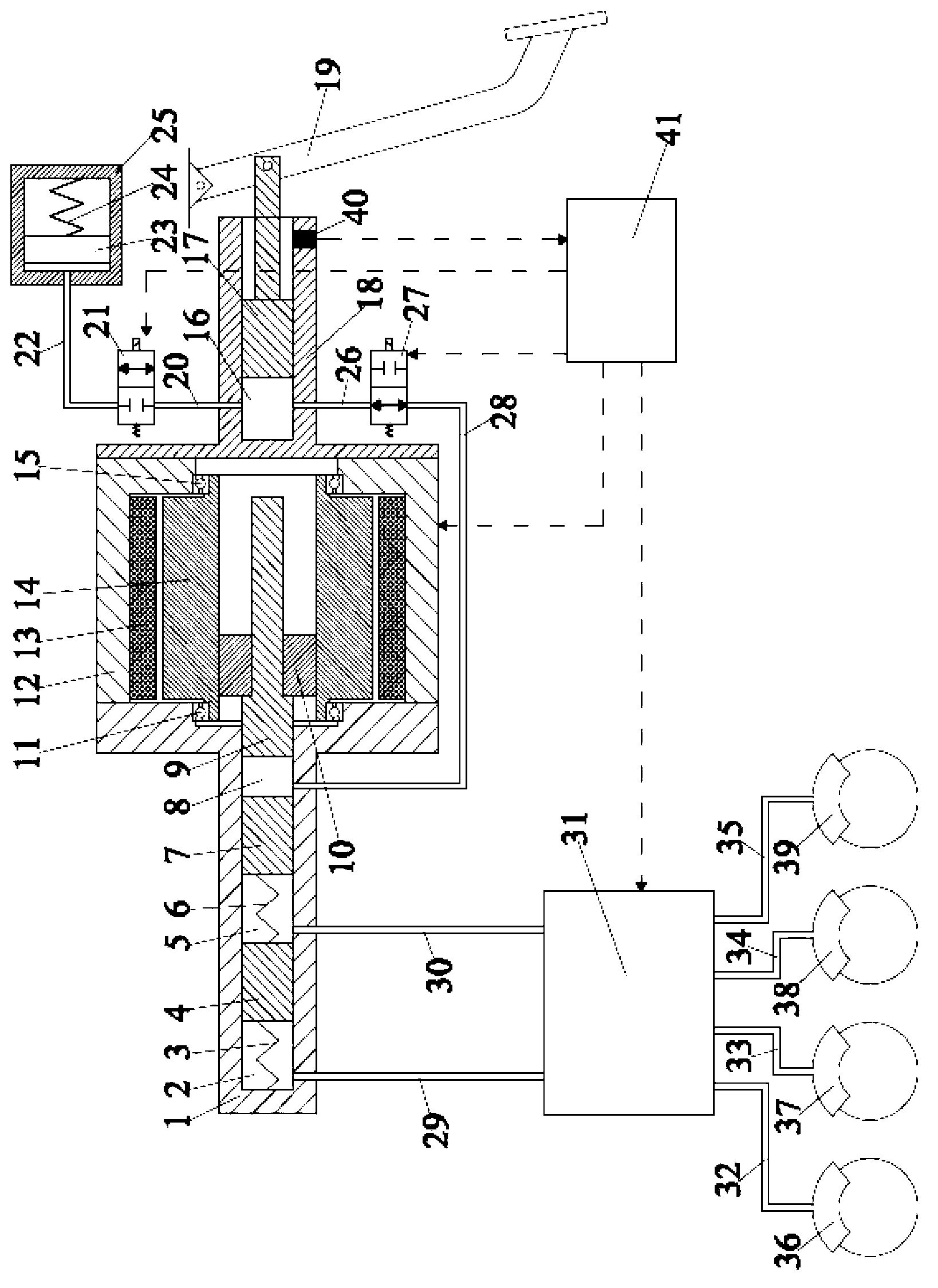
[0016] The automobile brake-by-wire system proposed by the present invention has a structure such as figure 1 As shown, it includes master cylinder shell 1, master cylinder first cavity piston 7, master cylinder first cavity spring 6, master cylinder second cavity piston 4, master cylinder second cavity spring 3, motor, nut 10, Screw rod 9, first bearing 11, second bearing 15, push rod housing 18, push rod 17, brake pedal 19, simulator valve 21, isolation valve 27, simulator, hydraulic control unit 31, left front brake 36, Right front brake 37, left rear brake 38, right rear brake 39.

[0017] The first inner chamber piston 7 of the master cylinder and the second inner chamber piston 4 of the master cylinder use the central valve piston used in the prior art; the first inner chamber piston 7 of the master cylinder and the second inner chamber piston 4 of the master cylinder are placed in the main cylinder In the cylinder shell 1; the first cavity piston 7 of the master cylind...


PUM


Abstract

The invention relates to a brake-by-wire system of an automobile and belongs to the technical field of automobile brake systems. In the brake system, a vacuum booster of the traditional vacuum booster hydraulic brake system is replaced with a motor, and a piston in a brake main cylinder is pushed to move to generate brake hydraulic pressure, so that dependence on vacuum degree of an engine is canceled; through the adoption of a pedal simulator, influences on feelings of a brake pedal during coordinated control of feedback and brake are eliminated; a hydraulic control unit of the traditional brake system is kept to implement hydraulic adjustment; and as a standby hydraulic brake system is integrated, braking with certain strength can be implemented by a driver under a situation that the power supply of the system is ineffective. Compared with the traditional distributed brake-by-wire scheme, the brake-by-wire system provided by the invention has the advantages as follows: the structure is changed when compared with the structure of the traditional vacuum booster hydraulic brake system, the system can be mounted on the automobile more conveniently, and more existing technologies in the traditional brake system can be succeeded in the control aspect.

Description

technical field [0001] The invention relates to an automobile braking system by wire, which belongs to the technical field of automobile braking systems. Background technique [0002] The development of hybrid electric vehicles and electric vehicles has put forward new requirements for the braking system of automobiles. The braking system used for hybrid electric vehicles and electric vehicles (called friction braking system to distinguish it from regenerative braking), in order to achieve good cooperation with the regenerative braking system of hybrid electric vehicles and electric vehicles, the brake On the basis of safety, the regenerative braking system can recover as much braking energy as possible. Firstly, the dependence on engine vacuum should be eliminated, and secondly, the coordinated control with the regenerative braking system should not affect the feeling of the brake pedal. In the existing vacuum-assisted hydraulic braking system, the vacuum booster depends o...

Claims


Application Information

Patent Timeline
Patent Type & Authority Applications(China)
IPC IPC(8): B60T13/66B60T13/74
Inventor 王治中于良耀王语风宋健
Owner TSINGHUA UNIV
Why Eureka
Try Eureka