Chemical vapor deposition (CVD) device

A technology of chemical vapor deposition and air intake device, which is applied in the direction of gaseous chemical plating, metal material coating process, coating, etc., can solve the problems of low film deposition rate, different heating temperature, and poor film quality, so as to avoid unavoidable The effect of breaking down, improving quality, and increasing speed

Active Publication Date: 2013-04-03
DEPOSITION EQUIP & APPL SHANGHAI LTD
View PDF6 Cites 12 Cited by
  • Summary
  • Abstract
  • Description
  • Claims
  • Application Information

AI Technical Summary

Problems solved by technology

Even when thin films are deposited, these films are porous and fall off easily
[0014] To sum up, the MOCVD device in the prior art heats the Group III metal-organic source and the Group V hydride source gas to the same temperature, and the quality of the final reaction-deposited film is very poor, and the film deposition rate is low and the producti

Method used


Image

  • Chemical vapor deposition (CVD) device
  • Chemical vapor deposition (CVD) device
  • Chemical vapor deposition (CVD) device

Examples


Embodiment 1

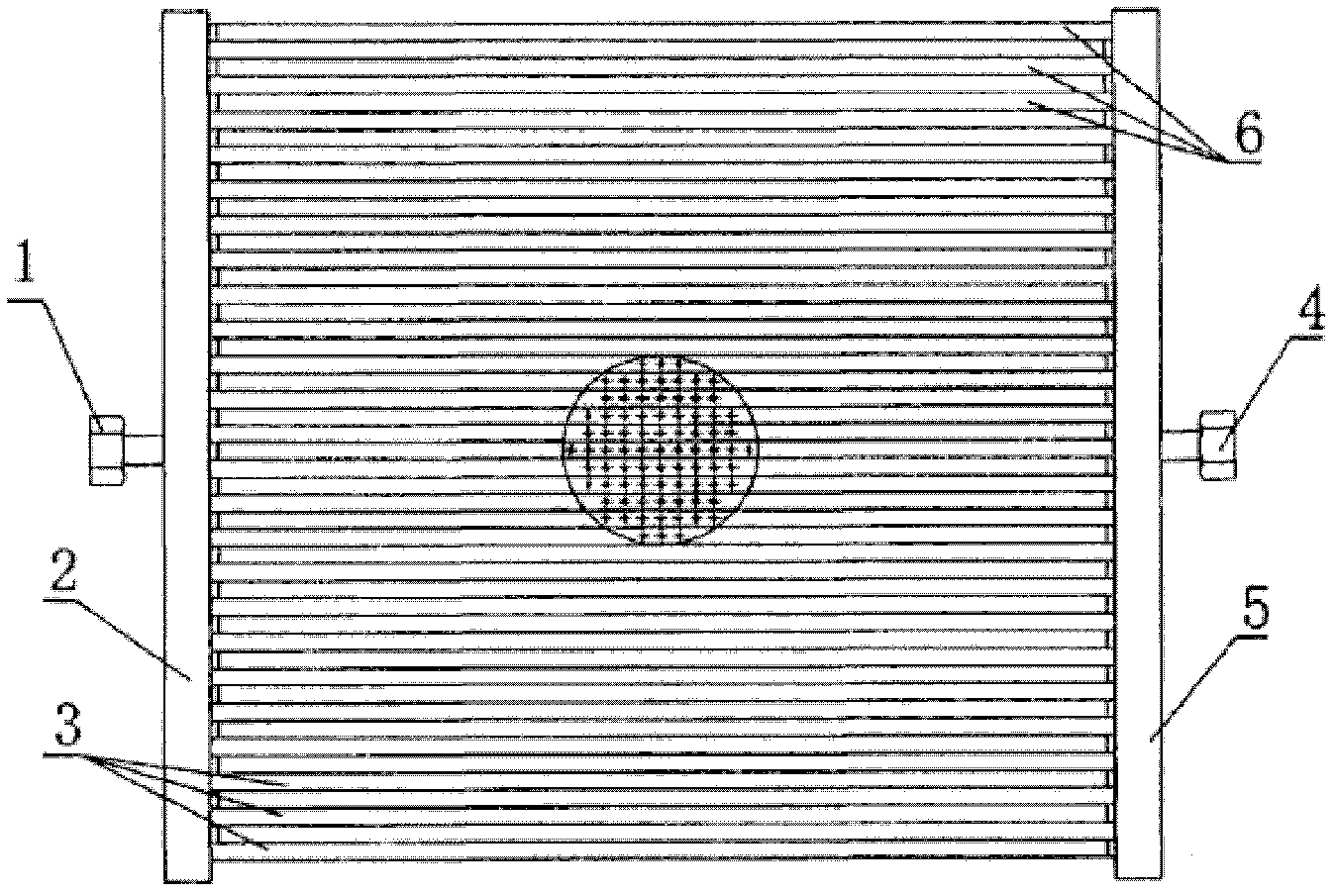
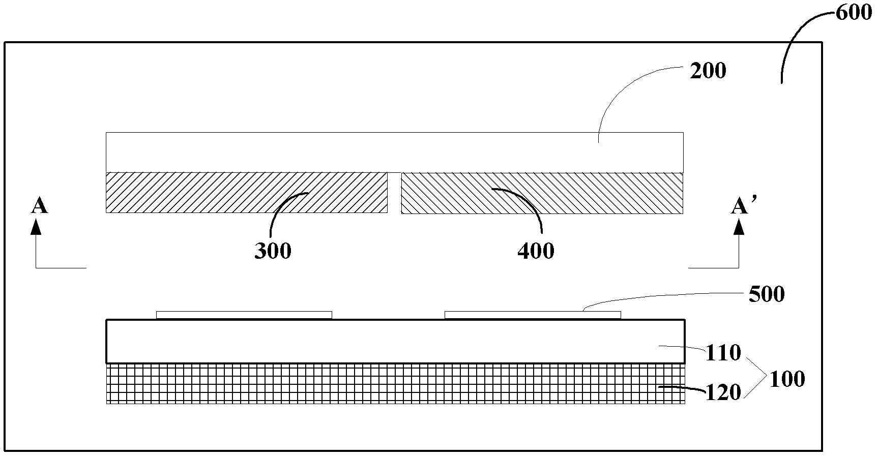
[0059] figure 2 is a schematic structural diagram of the CVD apparatus of this embodiment, image 3 is along figure 2 Schematic diagram of the structure obtained in the direction of AA'. Such as figure 2 and image 3 As shown, the CVD device described in this embodiment includes:

[0060] reaction chamber 600;

[0061] Cooling device 200;

[0062] The shower assembly located at the top of the reaction chamber 600, the shower assembly includes a first gas inlet device 300 and a second gas inlet device 400, which are used to transport the first gas and the second gas to the base 100 and the nozzle respectively. In the reaction zone between shower components, the heat transfer coefficient of the first air inlet device 300 is greater than the heat transfer coefficient of the second air inlet device 400;

[0063] The cooling device 200 is stacked with the first air intake device 300, the cooling device 200 is stacked with the second air intake device 400, and the first ai...

Embodiment 2

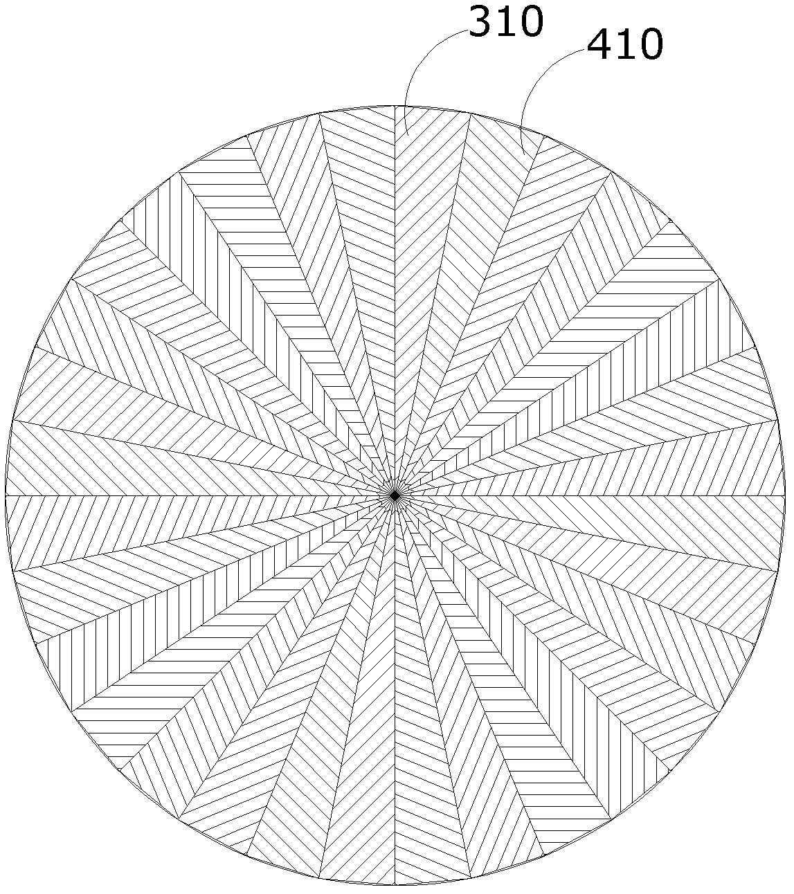
[0091] Figure 4 is a schematic structural diagram of a CVD device according to an embodiment of the present invention, Figure 5 is along Figure 4 Schematic diagram of the structure obtained in the middle BB' direction. see Figure 4 and Figure 5 As shown, the difference between this embodiment and Embodiment 1 is that: the gas diffusion pipe 310 in the first air intake device 300 and the gas diffusion pipe 410 in the second air intake device 400 are both rectangular, and the gas diffusion The tubes 310 and the gas diffusion tubes 410 are arranged alternately in sequence. During the heating process of the heating unit 120 , the first air intake device 300 and the second air intake device 400 have different temperatures.

[0092] In this embodiment, the first air intake device 300 and the second air intake device 400 are combined together, so that the structure of the entire shower assembly is relatively simple. The number and size of the gas diffusion tubes 310 and 410...


PUM


Abstract

The invention provides a chemical vapor deposition (CVD) device. The device comprises a reaction chamber, a cooling device, a spraying assembly arranged at the top of the reaction chamber and a base arranged opposite to the spraying assembly, wherein the base is provided with a heating unit; the spraying assembly comprises a first gas inlet device and a second gas inlet device which are respectively used for transmitting first gases and second gases to a reaction zone between the base and the spraying assembly; the cooling device and the first gas inlet device are stacked; the cooling device and the second gas inlet device are stacked; the first gas inlet device and the second gas inlet device are arranged side by side; the thermal conductivity of the first gas inlet device is greater than that of the second gas inlet device; and in the heating process of the heating unit, the first gas inlet device and the second gas inlet device have different temperatures. The device can provide different temperatures for gases in different gas inlet devices.

Description

technical field [0001] The invention relates to the technical field of chemical vapor deposition, in particular to a chemical vapor deposition device. Background technique [0002] Chemical vapor deposition (Chemical vapor deposition, referred to as CVD) is a chemical reaction of reacting substances under gaseous conditions, and the formation of solid substances is deposited on the surface of a heated solid substrate to obtain solid materials. It is realized by chemical vapor deposition equipment. . Specifically, the CVD device feeds the reaction gas into the reaction chamber through the gas inlet device, and controls reaction conditions such as pressure and temperature of the reaction chamber, so that the reaction gas reacts, thereby completing the deposition process steps. In order to deposit the desired film, it is generally necessary to feed a variety of different reactive gases into the reaction chamber, and it is also necessary to feed other non-reactive gases such as...

Claims


Application Information

Patent Timeline
IPC IPC(8): C23C16/455
Inventor 奚明马悦萨尔瓦多林芳黄占超
Owner DEPOSITION EQUIP & APPL SHANGHAI LTD
Why Eureka
Try Eureka