Invisible floor drain

A floor drain, invisible technology, applied in the direction of indoor sanitary pipe installations, waterway systems, drainage structures, etc., can solve the problems of many processes, waste of materials, time-consuming, etc., to reduce environmental pollution, improve bearing capacity, and smooth drainage. Effect

Active Publication Date: 2013-04-03
苏州苏明装饰股份有限公司
View PDF6 Cites 4 Cited by
  • Summary
  • Abstract
  • Description
  • Claims
  • Application Information

AI Technical Summary

Problems solved by technology

[0005] ① Floor drain installation requires accurate typesetting in advance, which takes a lot of time;
[0006] ②According to the typesetting layout, almost all the floor drains and sewer pipes need to be dismantled and re-constructed, wasting materials and manpower;
[0007] ③The position of the sewer pipe after re-laying the pipe needs to be re-hanged to take waterproof measures. There are many processes and it is easy to cause problems such as water seepage;
[0009] ⑤The floor drain is chosen to be in the middle of the joints of the four panels, and the four panels need to be cut precisely, which affects the overall decoration effect, is time-consuming, and requires relatively high requirements for operators

Method used


Image

  • Invisible floor drain
  • Invisible floor drain
  • Invisible floor drain

Examples


Embodiment 1

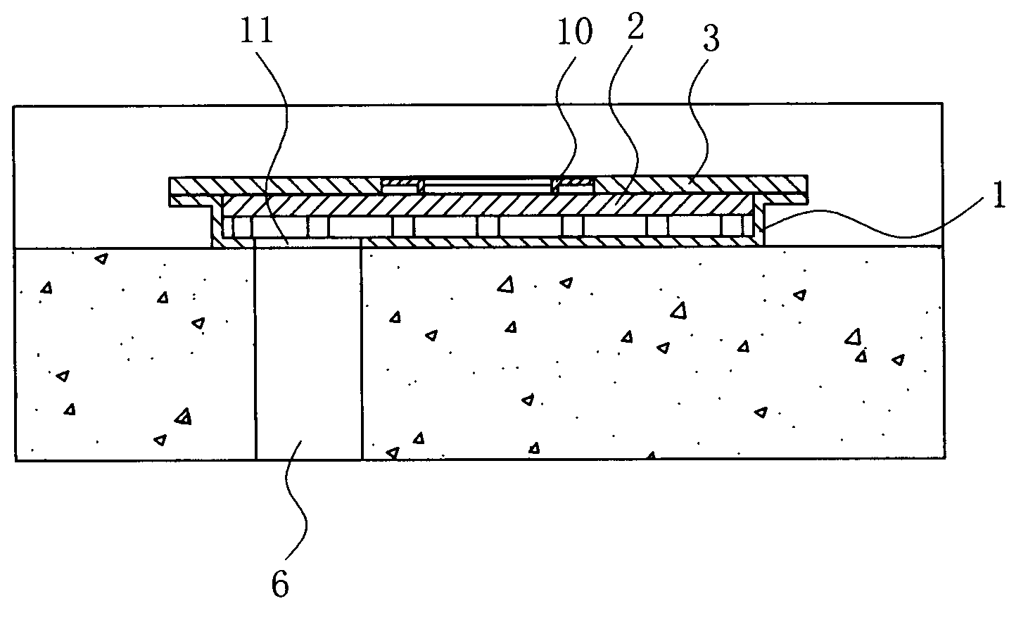
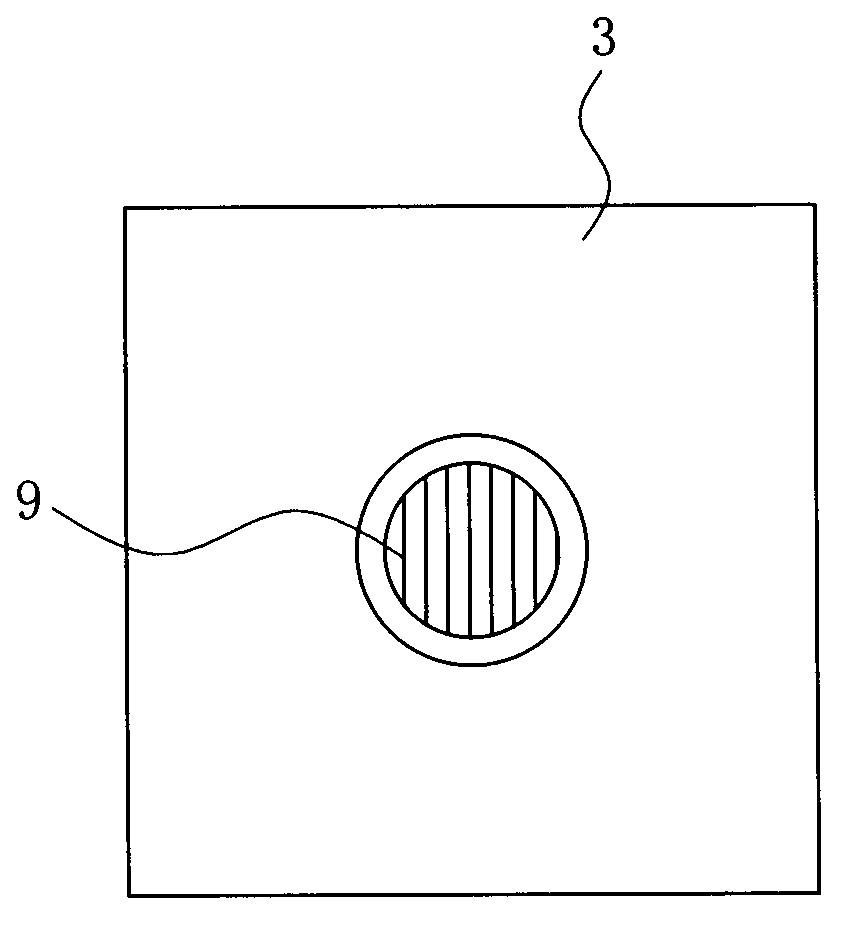
[0038] Embodiment one: see Figure 2-7 As shown, an invisible floor drain includes a base 1, a grid overhead layer 2 arranged in the base 1, and a surface material plate 3 arranged on the base 1, and the base 1 is integrally formed of PVC structure, the peripheral size of the base 1 matches the size of the surface material plate 3, the base 1 is composed of a concave base 4 and a flange 5 arranged on the outer edge of the concave base 4, and the concave base 4 corresponds to There is a drain hole 11 at the 6 places of the drain pipe, and the interface between the drain hole 11 and the drain pipe 6 is sealed with sealant, and the flange 5 on the outer edge of the concave base 4 can be used to support the surface plate 3 as load-bearing side.

[0039] In this embodiment, the face plate 3 is a floor tile, 30cm×30cm, such as Image 6 , 7 As shown, the grid overhead layer 2 is clamped in the concave base 4, the grid overhead layer 2 is a PVC integrally formed structure, and the ...

Embodiment 2

[0042] Embodiment 2: An invisible floor drain, the structure of which is basically similar to that of Embodiment 1, the difference is that the base is a ceramic integrally formed structure.

Embodiment 3

[0043] Embodiment 3: An invisible floor drain, the structure of which is basically similar to Embodiment 1, the difference is that: the base is made of stamped and bent metal plates; the grid overhead layer is composed of a metal grid layer and a 7×8 =56 metal pillars are welded and fixed, and one metal pillar is arranged at each intersection point of the metal grid layer.


PUM


Abstract

The invention discloses an invisible floor drain which is characterized by comprising a base, a latticed stilt floor arranged in the base, and a face material plate arranged on the base, wherein the base comprises an inwards concave seat and a raised edge on the outer edge of the inwards concave seat, a drain hole is formed in the position of the inwards concave seat corresponding to a sewer pipe, and the size of the periphery of the base is matched with that of the face material plate; the latticed stilt floor is clamped in the inwards concave seat and comprises a grid layer and a plurality of support pillars arranged below the grid layer, wherein the bottom surface of the latticed stilt floor is matched with the inner bottom surface of the inwards concave seat, and the top surface of the latticed stilt floor is flushed with the raised edge; and a mounting hole is formed in the middle of the face material plate, and a floor drain cover plate is arranged in the mounting hole. As the drain hole is formed in the base and in the position corresponding to the sewer pipe, and the face material plate is placed on the base, the invisible floor drain is achieved, the water drain pipe is not required to be modified, the construction is more convenient, and the construction time is reduced.

Description

technical field [0001] The invention relates to an indoor drainage device, in particular to an invisible floor drain. Background technique [0002] The floor drain is an important interface connecting the drainage pipe system with the indoor floor. As an important part of the drainage system in the residence, its performance directly affects the indoor air quality, whether the toilet drainage is smooth and so on. [0003] In the prior art, the floor drain usually includes a base 103 fixed on the decorative floor panel 101 (such as floor tiles) and communicated with the sewer pipe 102, and a filter screen (sieve) installed on the base 103. During installation, the The base 103 is installed in the center, that is, the floor drain is in the middle of the decorative floor panel 101 (in the middle of the diagonal line) or in the middle of the joints of the four panels, such as figure 1 , 2 As shown, this is to realize that each small decorative floor plate 101 is inclined towar...

Claims


Application Information

Patent Timeline
IPC IPC(8): E03C1/282E03F5/04
Inventor 管勇美许超
Owner 苏州苏明装饰股份有限公司
Why Eureka
Try Eureka