Manufacturing method of heat insulation decorative line

A technology of decorative lines and production methods, applied in chemical instruments and methods, lamination devices, lamination auxiliary operations, etc., can solve problems such as complex construction, inability to form, poor decorative effect, etc., to ensure uniformity and consistency, Guaranteed decorative effect and good decorative effect

Active Publication Date: 2013-04-03
ASIA CUANON TECH SHANGHAI
View PDF3 Cites 7 Cited by
  • Summary
  • Abstract
  • Description
  • Claims
  • Application Information

AI Technical Summary

Problems solved by technology

[0003] One is the line of the thin plastering system, which is formed by cutting the EPS board of the corresponding specification, pasting it on the wall, and then applying mortar, hanging grid cloth, scraping putty, and painting the finishing paint on the EPS board , its advantage is that it can be made into any shape, light in weight, and the disadvantage is that the decoration effect is poor, there are many on-site installation procedures, and the construction is complicated;
[0004] One is to use aluminum-plastic panels to fold into corresponding line shapes, and then install them on the wall, which has the advantages of good decorative effect and light weight; the disadvantage is that it can only make simple lines with larger cross-sections combined with straight lines, which is difficult for complex structures. Or lines with arc surfaces cannot be formed, and the processing process is done by hand, and the processing speed is slow;
[0005] One is the marble line, which is made by grinding the marble as a whole according to the shape of the line or grinding it in pieces and then splicing it. Its advantage is excellent decorative effect, but its disadvantages are heavy weight and extremely slow processing speed. Generally, dry hanging type is used for installation. slow, expensive, etc.

Method used


Image

  • Manufacturing method of heat insulation decorative line
  • Manufacturing method of heat insulation decorative line

Examples


Embodiment Construction

[0042]In order to understand the above-mentioned purpose, features and advantages of the present invention more clearly, the present invention will be further described in detail below in conjunction with the accompanying drawings and specific embodiments. It should be noted that, in the case of no conflict, the embodiments of the present application and the features in the embodiments can be combined with each other.

[0043] In the following description, many specific details are set forth in order to fully understand the present invention. However, the present invention can also be implemented in other ways than described here. Therefore, the protection scope of the present invention is not limited by the specific implementation disclosed below. Example limitations.

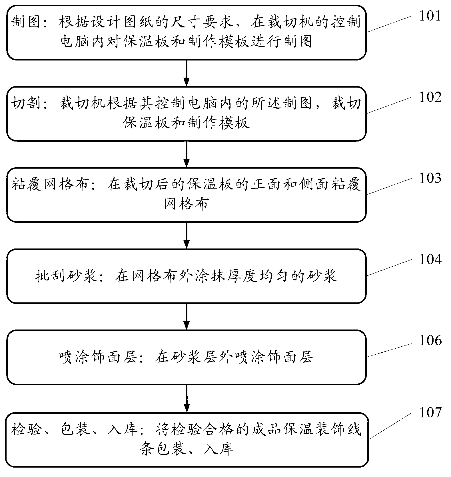
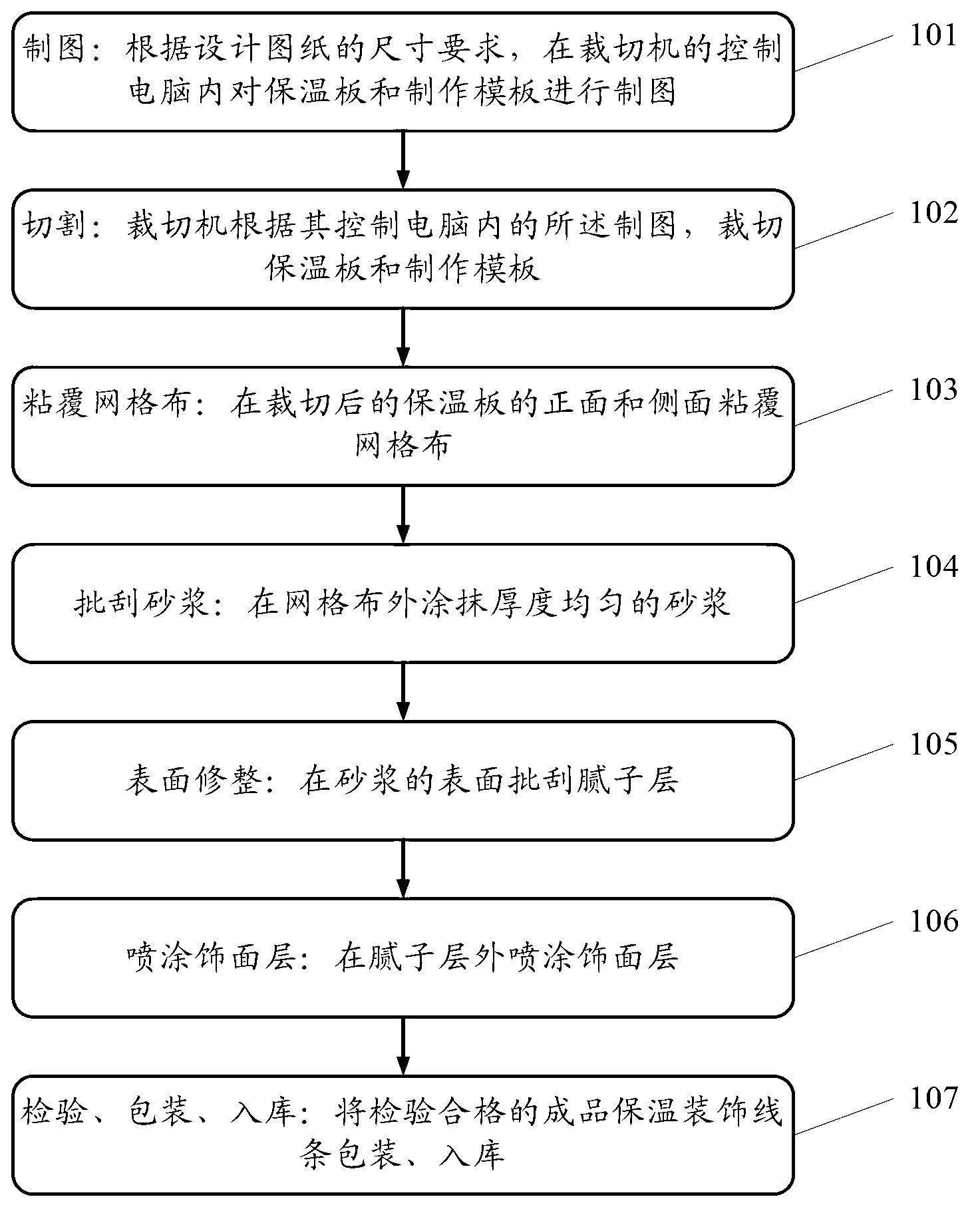
[0044] figure 1 It is a flow chart of an embodiment of the method for making thermal insulation decorative lines according to the present invention.

[0045] Such as figure 1 As shown, the present invention...


PUM


Abstract

The invention provides a manufacturing method of a heat insulation decorative line. The manufacturing method comprises the following steps: step 101: drawing: drawing a heat insulation plate and a manufacturing template in a control computer of a cutting machine according to the dimensional requirements of a design drawing; step 102: cutting: cutting the heat insulation plate and the manufacturing template by the cutting machine according to the drawing in the control computer; step 103: sticking and covering grid cloth: sticking and covering the grid cloth on the front surface and the side surface of the heat insulation plate after cutting; step 104: scraping mortar: smearing the mortar with uniform thickness outside the grid cloth; step 105: finishing the surface: scraping a putty layer on the surface of the mortar; step 106: spraying a finish coat: spraying the finish coat outside the mortar; and step 107: inspecting, packaging and warehousing: packaging and warehousing a finished product, namely the heat insulation decorative line, which is inspected to be qualified. According to the technical scheme provided by the invention, the manufactured heat insulation decorative line has the advantages of light weight, good decoration effect, convenience in processing and mounting and high performance-cost ratio.

Description

technical field [0001] The invention relates to the field of building thermal insulation decoration, and more specifically, to a method for making thermal insulation decorative lines. Background technique [0002] As an integral part of building decoration, lines have been used in architecture. Traditional lines generally have the following production methods: [0003] One is the line of the thin plastering system, which is formed by cutting the EPS board of the corresponding specification, pasting it on the wall, and then applying mortar, hanging grid cloth, scraping putty, and painting the finishing paint on the EPS board , its advantage is that it can be made into any shape, light in weight, and the disadvantage is that the decoration effect is poor, there are many on-site installation procedures, and the construction is complicated; [0004] One is to use aluminum-plastic panels to fold into corresponding line shapes, and then install them on the wall, which has the adv...

Claims


Application Information

Patent Timeline
Patent Type & Authority Applications(China)
IPC IPC(8): E04F19/02B32B37/02B32B13/14B32B38/00B32B27/12
Inventor 孙先海李金钟徐志新
Owner ASIA CUANON TECH SHANGHAI
Why Eureka
Try Eureka