Oil filler cap assembly

A technology of oil filling port cover and oil filling port, which is applied in the direction of adding/discharging lubricant and lubricating parts, etc., which can solve problems such as poor ventilation, increased engine pressure, personal safety issues, etc., and achieves simple structure and avoids interior The effect of increasing pressure and protecting work safety

Inactive Publication Date: 2013-04-03
SHUNDA WUHU AUTOMOBILE DECORATION
View PDF6 Cites 5 Cited by
  • Summary
  • Abstract
  • Description
  • Claims
  • Application Information

AI Technical Summary

Problems solved by technology

[0004] However, while the engine crankcase ventilation system brings a lot of convenience, its existing defects are also becoming more and more prominent: when working in low temperature areas or in high-speed driving in winter and other low-temperature environments, the above-mentioned crankcase gas hose leaves the engine section. The distance from the temperature drops sharply, and the steam from the engine turns into water when it reaches the hose, and then affected by the regional temperature or the air flow during high-speed driving, the water in the hose will freeze and block the hose
Once the water in the pipe condenses into ice, it will directly cause the water vapor generated in the cylinder to be unable to be discharged normally, resulting in blockage of the crankcase ventilation system pipe, poor ventilation, and increased internal pressure of the engine; what's more, when the internal pressure of the engine When it is higher than the limit that the crankshaft oil seal and each sealing surface can withstand, the oil seal and each sealing surface will leak oil. In severe cases, the crankshaft oil seal will fall off, and the engine will be scrapped, which will cause personal safety problems

Method used


Image

  • Oil filler cap assembly
  • Oil filler cap assembly
  • Oil filler cap assembly

Examples


Embodiment Construction

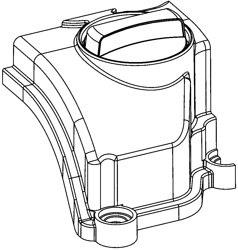
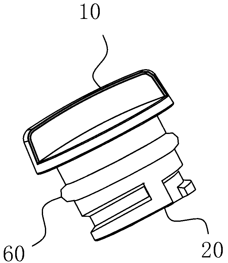
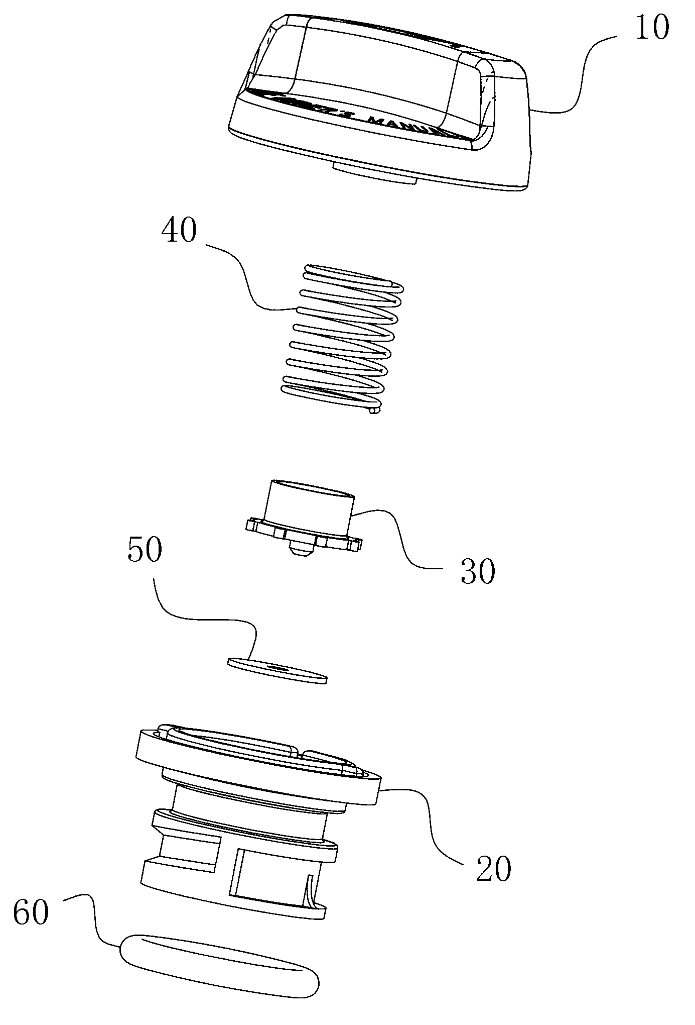
[0012] An oil filler cap assembly, the fuel filler cap assembly has a one-way valve structure, at least including an upper cover 10, and a valve housing located under the upper cover 10 for forming a plug-in and airtight fit with the fuel filler part 20 and a valve core 30 arranged in the valve housing part 20; the valve housing part 20 is cylindrical in shape and its bottom is opened with a hole 21 through the bottom wall, and the valve core 30 is connected with the upper cover 10 and / or The valve housing parts 20 form an elastic fit, and the elastic direction is parallel or intersected with the axial direction of the valve housing part 20. The bottom of the valve core 30 extends to the bottom wall of the valve housing part 20 and forms a gap between the upper channel 21 and the elastic direction. The openable and closable surfaces are abutted against each other; there is a gap between the valve core 30 and the inner wall of the valve housing 20 and the gap is set along with t...


PUM


Abstract

The invention belongs to the field of automobile engine fittings, and particularly relates to an oil filler cap assembly. The oil filler cap assembly is in a structure of a one-way valve, and at least comprises an upper cover, a valve casing part and a valve core, wherein the valve casing part is in a tube shape, the bottom of the valve casing part is provided with a hole passage which penetrates through the bottom wall of the valve casing part, the valve core is in elastic fit with the upper cover and / or the valve casing part, the elastic direction of the valve core is parallel with or intersected with the axis direction of the valve casing part, the bottom of the valve core extends towards the bottom wall of the valve casing part and is in abutting fit with an open-and-close type surface which is arranged in the hole passage of the valve casing part and acts towards the elastic direction, a gap is arranged between the valve core and the inner wall of the valve casing part, and the gap extends and communicates the outside ambient environment. The oil filler cap assembly has the advantage that the one-way valve mechanism is integrated on the basis of the original oil filler cap, the structure is simple, the practicality and convenience are realized, and the problems of increasing of internal pressure of the engine and the subsequent falling of an oil seal and oil leakage of a sealing surface due to blockage of ventilating driving pipes caused by icing of pipelines are solved, so the safety of the engine and the personnel is effectively protected.

Description

technical field [0001] The invention belongs to the field of automobile engine accessories, and in particular relates to an oil filler cap assembly. Background technique [0002] When the engine is working, a part of the combustible mixture and exhaust gas will always escape into the crankcase through the piston ring, and the gasoline vapor condensed into the crankcase will make the engine oil thinner and the performance will deteriorate. The exhaust gas contains water vapor and sulfur dioxide. The water vapor condenses in the engine oil to form foam, which damages the oil supply. This phenomenon is especially serious in winter; sulfur dioxide meets water to form sulfurous acid, and sulfurous acid forms sulfuric acid when it meets oxygen in the air. The appearance of oil not only deteriorates the oil, but also corrodes the parts. As the combustible mixture and exhaust gas escape into the crankcase, the pressure in the crankcase will increase, and the engine oil will seep fr...

Claims


Application Information

Patent Timeline
IPC IPC(8): F01M11/04
Inventor 郎玉山
Owner SHUNDA WUHU AUTOMOBILE DECORATION
Why Eureka
Try Eureka