High-supercharged two-stroke direct injection engine and ventilation method thereof

An in-cylinder direct injection and engine technology, which is applied to internal combustion piston engines, combustion engines, machines/engines, etc., can solve the problems of high combustion consumption rate and pollutant emissions, enhance active control capabilities, and reduce harmful emissions. , the effect of avoiding consumption

Inactive Publication Date: 2013-04-03
XIHUA UNIV
View PDF5 Cites 4 Cited by
  • Summary
  • Abstract
  • Description
  • Claims
  • Application Information

AI Technical Summary

Problems solved by technology

However, its high combustion consumption rate and pollutant emissions make it gradually abandoned by the market

Method used


Image

  • High-supercharged two-stroke direct injection engine and ventilation method thereof
  • High-supercharged two-stroke direct injection engine and ventilation method thereof

Examples


Embodiment 1

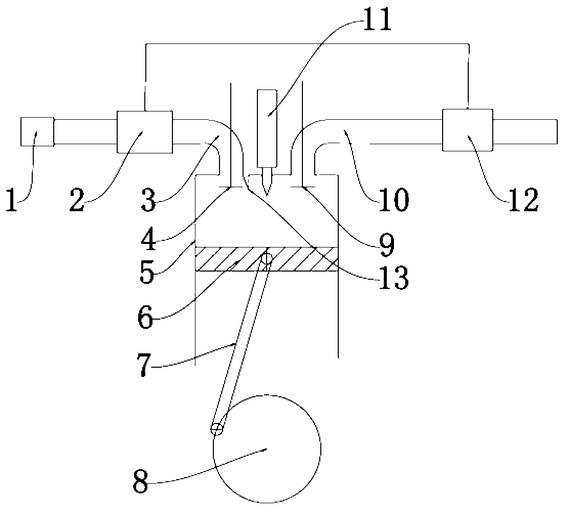
[0029] see figure 1 . The highly boosted two-stroke in-cylinder direct injection engine described in this embodiment includes a cylinder 5, a piston 6 is installed in the cylinder, and the piston 6 is connected to a crankshaft 8 through a connecting rod 7. A fuel injector 11 is installed at the center of the top wall of the cylinder 5 for injecting fuel into the cylinder 5 . An intake hole and an exhaust hole are also arranged on the top wall of the cylinder 5, and the fuel injector 11 is located at the midpoint of the line between the intake hole and the exhaust hole. An intake valve 4 is installed on the intake hole, and the intake hole communicates with the intake passage 3. An air filter 1 and a high-pressure ratio supercharger 2 are installed on the intake passage 3. The air filter 1 is located at the high-pressure than Supercharger 2 before. An air guide screen 13 is arranged on the edge of the air intake hole, and the air guide screen 13 is located on one side of the...

Embodiment 2

[0032] This embodiment is to illustrate the ventilation method of the high-pressure two-stroke direct-injection engine described in Embodiment 1. The high pressure ratio supercharger 2 supercharges the fresh air to more than 0.6MPa, on the one hand, it is convenient to replace the exhaust gas in the cylinder, and on the other hand, it maintains a higher initial pressure inside the cylinder. After the piston 6 completes the work of the previous cycle, the exhaust valve 9 is opened before the bottom dead center of this cycle, and the engine starts the free exhaust process. Piston 6 begins to move upward after turning over the bottom dead center, and the engine enters the forced exhaust stage. At a certain moment after the bottom dead center, the intake valve 4 opens, and the high-pressure fresh air in the intake passage 3 enters the cylinder 5 after passing through the intake valve 4. The burned gas in the cylinder is replaced, and part of the fresh air mixed with the burned ga...


PUM


Abstract

The invention discloses a high-supercharged two-stroke direct injection engine and a ventilation method thereof. The engine comprises an air cylinder; a piston is arranged in the air cylinder; the piston is connected with a crankshaft through a connecting rod; the center of the top wall of the air cylinder is provided with an oil sprayer; the top wall of the air cylinder is also provided with an air inlet and an exhaust vent; the air inlet is provided with an inlet valve; the air inlet is communicated with an admission passage; the admission passage is provided with a high-pressure ratio supercharger; the exhaust vent is provided with an exhaust valve; and the exhaust vent is communicated with an exhaust passage. In a loop, according to the rotation angle of the crankshaft, the exhaust valve is opened before the piston reaches a bottom dead center for 45 DEG and is closed after the piston bypasses the bottom dead center for 60 DEG; the inlet valve is opened after the piston bypasses the bottom dead center for 15 DEG and is closed before the piston reaches a top dead center for 85 DEG; and the inlet valve is closed after the exhaust valve is closed. The engine disclosed by the invention has the advantages that the structure is compact; the manufacturing difficulty is reduced; air intake and exhaust are controllable; the power weight ratio is greatly improved; and moreover, fuel economy and emission level which approach to that of a four-stroke engine can be realized.

Description

technical field [0001] The invention belongs to the field of engines, and in particular relates to a two-stroke engine. Background technique [0002] In the century-old history of engine development, two-stroke engines have always had their unique advantages, such as simple structure, light weight, small size, low cost, and stable operation. [0003] The structure and working principle of the two-stroke gasoline engine show that it uses the combustible mixture in the crankcase or the fresh air in the crankcase to purge the exhaust gas after combustion, so it is inevitable to discharge the combustible gas out of the engine. At the same time, the lubricating oil in the crankcase is inevitably mixed into the air for combustion, thereby increasing the consumption of lubricating oil, which is also not conducive to reducing the HC emissions of the engine. Since the two-stroke engine uses fresh mixed gas to scavenge, the higher the load, the more fresh mixed gas will be lost, and ...

Claims


Application Information

Patent Timeline
Patent Type & Authority Applications(China)
IPC IPC(8): F02B33/00F02B25/00
CPCY02T10/146Y02T10/12
Inventor 田维曾东建韩志强邓猛彭义增任川江
Owner XIHUA UNIV
Why Eureka
Try Eureka