Mixing circular incinerator

An incinerator, circular technology, applied in the incinerator, combustion type, combustion method and other directions, can solve the problems of collision, increase the difficulty of operating the incinerator, and the air supply branch pipe cannot continue to rotate, and achieve the effect of preventing friction.

Active Publication Date: 2013-04-03
YAMATO SANKO MFG
View PDF8 Cites 3 Cited by
  • Summary
  • Abstract
  • Description
  • Claims
  • Application Information

AI Technical Summary

Problems solved by technology

If the above problems are not solved and the operation continues, the air outlet will collide with the hearth surface of the incinerator, causing the air supply branch pipe to fail to continue to rotate.
[0004] On the other hand, the amount of calorific value of sewage sludge to be treated varies from one another, and some sewage sludge containing sand also has regional characteristics, which increases the difficulty in operating the incinerator

Method used


Image

  • Mixing circular incinerator
  • Mixing circular incinerator
  • Mixing circular incinerator

Examples


Embodiment 1

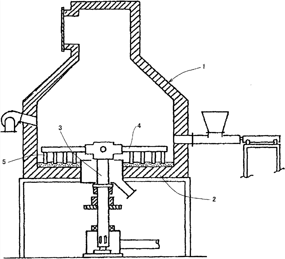
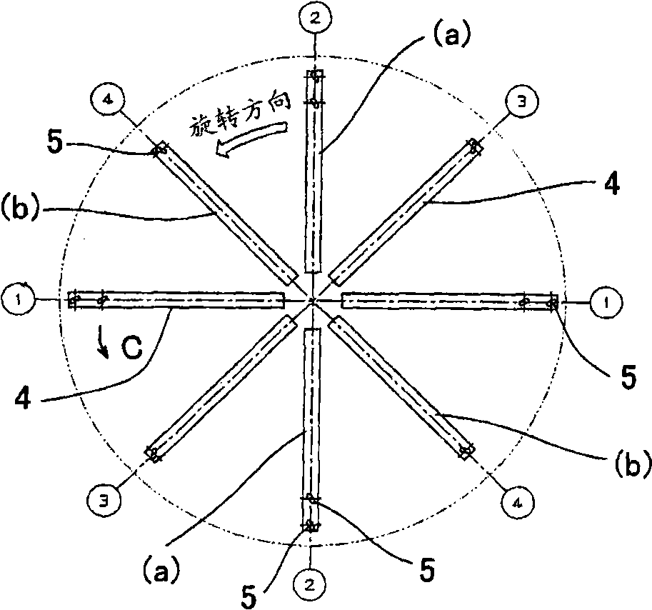
[0034] figure 1 A schematic longitudinal sectional view of the stirring circular incinerator 1 of the present invention is shown. This agitated circular incinerator 1 is provided with a rotary air supply shaft tube 3 protruding from its lower side to the inside of the furnace at the center of the hearth 2 in the circular furnace, and from the top of the rotary air supply shaft tube 3 A plurality of rotating arms (hereinafter referred to as air supply branch pipes) 4 are radially extended, and a plurality of air supply branch pipes 5 are formed protruding from the surface of each of the air supply branch pipes 4 toward the hearth 2 .

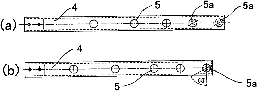
[0035] For the front end of each air supply branch pipe 5 among the plurality of air supply branch pipes 5 or the air supply branch pipe 5a located at the front end and its inner side, its cross-sectional shape is set to a flat shape, and relative to the air supply branch pipe The extending direction of 4 is installed obliquely, so that the proc...


PUM


Abstract

A mixing circular incinerator of the invention can effectively treat sewage and mud. Furthermore a deflecting part of each air feeding branch pipe is supported through heat-resistant small particles which are laid on an incinerator bed, and furthermore the thickness is approximately adjusted for preventing damage of the incinator bed surface. The mixing circular incinerator provided by the invention is characterized in that: the central part of the incinerator is provided with a rotatable air feeding shaft pipe which can rotate freely; air feeding branch pipes radially extend from the rotatable air feeding shaft pipe; and each air feeding branch pipe is provided with a plurality of air feeding sub-branch pipes, wherein, heat-resistant small particles which can move freely are laid on the flat heat-resistant incinerator bed of the incinerator. Furthermore the height of a lock gate equipped at the rotatable air feeding shaft pipe side is adjusted correspondingly to extension height of the air feeding branch pipe. The height of the lock gate is used as laying thickness of the heat-resistant small particles. The air feeding branch pipes are respectively provided at the positions where the lower end of the air feeding sub-branch pipes at the front side of each air feeding branch pipe can contact with the heat-resistant small particles or be embedded into the heat-resistant small particles.

Description

technical field [0001] The present invention relates to an agitating circular incinerator which blows out the air exhausted from the rotating air supply branch pipe from the air supply branch pipe, and at the same time stirs and burns the treated matter, and provides the possibility of drying and burning the treated matter in the incinerator so that even the This is a stirring circular incinerator that can also incinerate processed materials with a high water content such as sludge. Background technique [0002] In recent years, there has been a demand for a treatment device capable of reducing the amount of sludge with a high water content in sewage and the like and performing incineration treatment. A device that combines a dryer and an agitating circular incinerator has attracted attention as a device that achieves the above-mentioned purpose. However, as mentioned above, unlike conventional sludge treatment, sewage sludge with a high water content has a large volume and...

Claims


Application Information

Patent Timeline
Patent Type & Authority Applications(China)
IPC IPC(8): F23G7/00F23G7/04F23L1/00
Inventor 荒井正太郎登家章司久保田信二
Owner YAMATO SANKO MFG
Why Eureka
Try Eureka