Liquefaction system for producing LNG (Liquefied Natural Gas) by using pressure energy of pipeline

A pipeline pressure and channel technology, applied in the field of liquefaction system, can solve the problems of high energy consumption, extra power consumption required by the system, low utilization rate of pressure energy, etc., and achieve the effect of reducing purification pressure

Active Publication Date: 2013-04-03
TECHNICAL INST OF PHYSICS & CHEMISTRY - CHINESE ACAD OF SCI
View PDF6 Cites 24 Cited by
  • Summary
  • Abstract
  • Description
  • Claims
  • Application Information

AI Technical Summary

Problems solved by technology

The expansion work in the patent CN202139209 is not utilized, and the system requires additional power consumption
In the patent CN1409812A, the expanded gas in the pre-cooling branch is recompressed and then returned to circulation, which can improve the liquefaction rate of the system but consume a lot of energy
To sum up, some of the exist

Method used


Image

  • Liquefaction system for producing LNG (Liquefied Natural Gas) by using pressure energy of pipeline
  • Liquefaction system for producing LNG (Liquefied Natural Gas) by using pressure energy of pipeline
  • Liquefaction system for producing LNG (Liquefied Natural Gas) by using pressure energy of pipeline

Examples


Embodiment 1

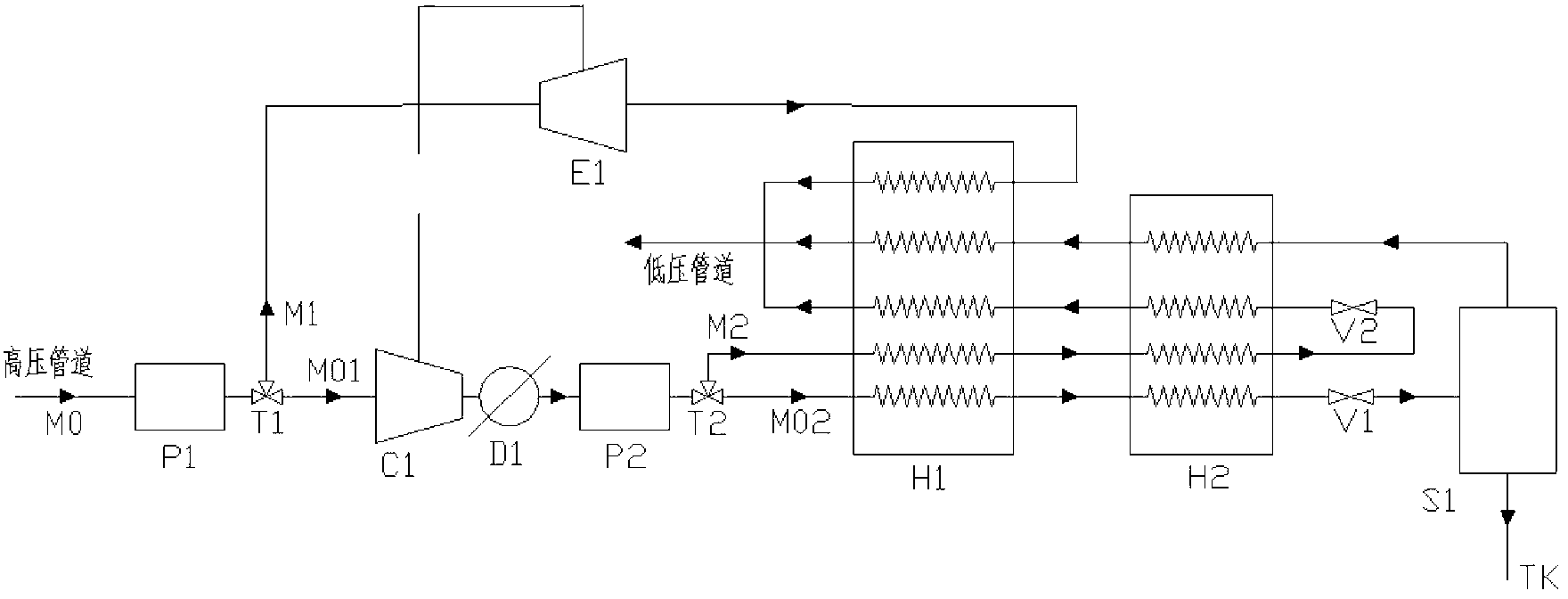
[0031] Embodiment 1: as figure 1 As shown, the liquefaction system in this embodiment 1 includes a primary purifier P1, a secondary purifier P2, a first compressor C1, a first cooler D1, a first expander E1, a first recuperator H1, The second regenerative heat exchanger H2, the first throttle valve V1, the second throttle valve V2 and the gas-liquid separator S1;

[0032]The natural gas from the high-pressure pipeline is first roughly purified and dehydrated by the primary purifier P1, and then divided into two paths after the first distribution valve T1, the two paths are the first pre-cooling branch M1 and the first liquefaction branch M01;

[0033] The natural gas flow entering the first liquefaction branch M01 flows through the first compressor C1 and the first cooler D1 to be compressed and cooled in sequence; then enters the secondary purifier P2, where acid gas and gas are removed After the impurities are deeply purified, they are divided into two paths after the secon...

Embodiment 2

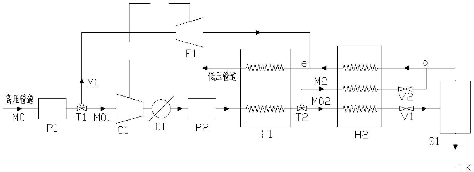
[0041] Such as figure 2 As shown, the difference between this embodiment 2 and embodiment 1 is:

[0042] The second distribution valve T2 is located between the first regenerative heat exchanger H1 and the second regenerative heat exchanger H2;

[0043] The outlet pipeline of the second throttle valve V2 in the main cooling branch M2 is connected to the liquefaction branch M02 at d of the upper outlet pipeline of the gas-liquid separator S1; the outlet of the first expander E1 of the first precooling branch M1 The pipeline is connected to the liquefaction branch M02 at point e between the first recuperation heat exchanger H1 and the second recuperation heat exchanger H2;

[0044] The rest of the system is the same as in Embodiment 1.

[0045] Compared with Embodiment 1, the system in Embodiment 2 has the advantage that the first recuperative heat exchanger H1 has two channels, and the second recuperative heat exchanger H2 has three channels, and its manufacturing difficulty...

Embodiment 3

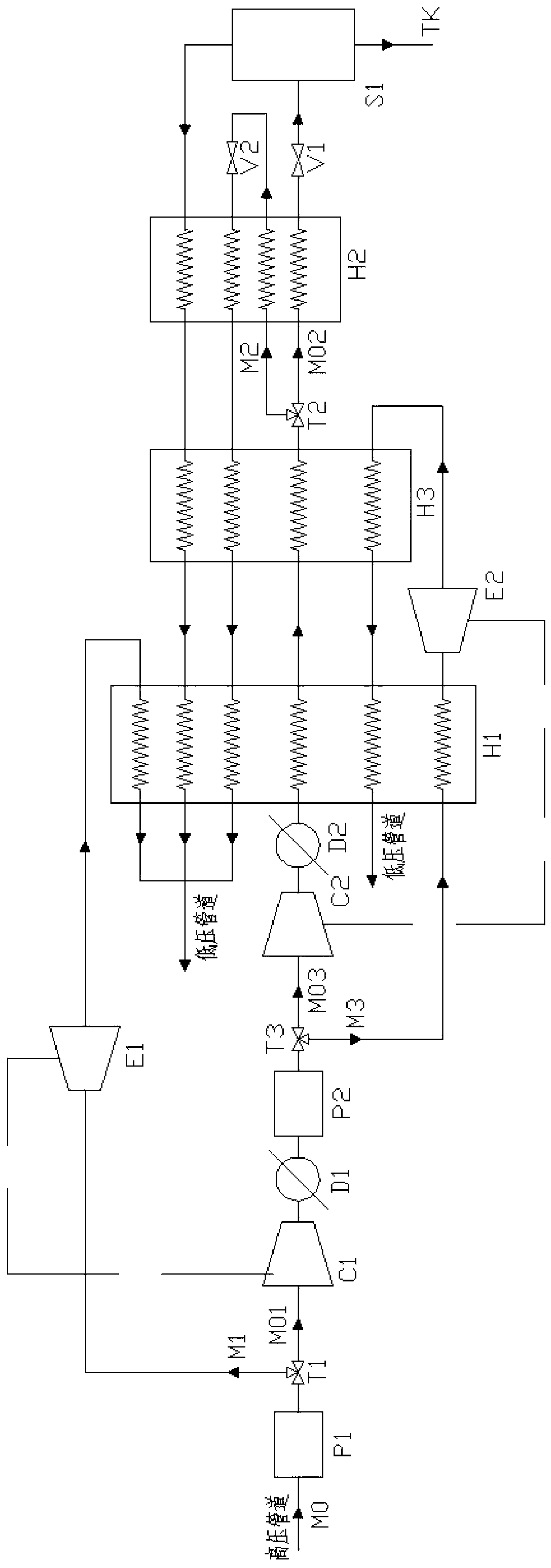
[0047] Such as image 3 As shown, the difference between Embodiment 3 and Embodiment 1 is that the throttling expansion device of the main cooling branch M2 selects the second expander E2, and adds the second compressor C2 and the second cooler D2, specifically:

[0048] After the main cooling branch M2 is separated from the distribution valve T2 at the outlet of the secondary purifier P2, it enters the second expander E2 through the second high-pressure channel of the first recuperator H1, and expands through the second expander E2 The final natural gas flows through the second low-pressure passage of the second recuperator H2 and the second low-pressure passage of the first recuperator H1 to recover cooling capacity, and finally enters the low-pressure pipeline;

[0049] The natural gas in the first liquefaction branch M01 comes out of the secondary purifier P2, passes through the second compressor C2 and the subsequent second cooler D2, and then enters the first high-pressu...


PUM


Abstract

The invention relates to a gas liquefaction system, and particularly relates to a liquefaction system for producing LNG (Liquefied Natural Gas) by using pressure energy of a pipeline. Natural gas from a high-pressure pipe is divided into natural gas in a liquefaction branch, natural gas in a first pre-cooling branch and natural gas in a main cooling branch, wherein the natural gas in the liquefaction branch is from the high-pressure pipeline, is sequentially compressed and cooled, then obtains heat in a backheating heat exchanger, and enters a gas-liquid separator after being throttled; a separated liquid phase is produced LNG; a gas phase enters a low-pressure pipeline after the cold energy is recycled by the backheating heat exchanger; the natural gas in the first pre-cooling branch enters the low-pressure pipeline after being expanded by an expanding machine after the cold energy is recycled in a heat regenerator; and the natural gas in the main cooling branch and the natural gas in the liquefaction branch are separated behind a cooler, the natural gas in the main cooling branch is cooled by the backheating heat exchanger and then throttled and expanded, and finally enters the low-pressure pipeline after the cold energy is recycled by the backheating heat exchanger. According to the liquefaction system, the LNG can be produced by using the pressure of the pipelines, compressors are driven by output works of the expanding machine without additional energy consumption.

Description

technical field [0001] The invention relates to an LNG liquefaction system in the field of energy and chemical industry, in particular to a liquefaction system for producing LNG by using pipeline pressure energy. Background technique [0002] Natural gas is a high-quality and efficient clean energy and chemical raw material, which is widely used in various fields of national economic construction. Nearly 90% of my country's natural gas reserves are concentrated in the central and western regions, and are mainly transported to the east by the gas pipeline network. Currently, the annual designed natural gas transmission capacity is 90 billion m 3 -100 billion m 3 . Depending on the design of the main natural gas pipeline, the delivery pressure is between 4 and 10 MPa. After being delivered to the destination, it is usually decompressed by a multi-stage decompression station to below 0.5-1.2 MPa for reuse. This decompression process usually adopts direct throttling, of which ...

Claims


Application Information

Patent Timeline
IPC IPC(8): F25J1/00
CPCF25J1/0022F25J1/0037F25J1/004F25J1/0045F25J1/0201F25J1/0232F25J2230/30F25J2270/06
Inventor 公茂琼程逵炜吴剑峰
Owner TECHNICAL INST OF PHYSICS & CHEMISTRY - CHINESE ACAD OF SCI
Why Eureka
Try Eureka